COMMUNICATION
NOTE For Europe, the emergency switch requirements are detailed in Harmonized document
REPO Connections
Wire Function | Terminal Wire Size Rating | Suggested Wire Size | |
|
|
|
|
REPO | L1 | 0.82 mm2 (18 AWG) | |
|
| ||
| L2 | ||
|
|
| |
|
|
|
|
NOTE Leave the REPO connector installed in the REPO port on the UPS even if the REPO function is not needed.
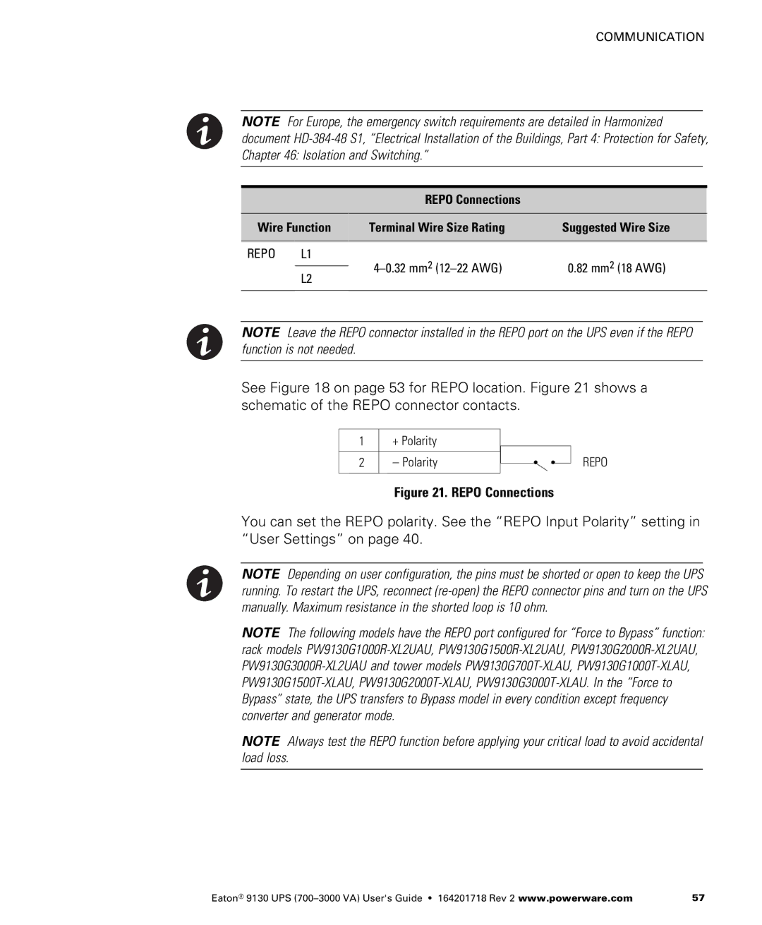
See Figure 18 on page 53 for REPO location. Figure 21 shows a schematic of the REPO connector contacts.
1+ Polarity
2 – Polarity
REPO
Figure 21. REPO Connections
You can set the REPO polarity. See the “REPO Input Polarity” setting in “User Settings” on page 40.
NOTE Depending on user configuration, the pins must be shorted or open to keep the UPS running. To restart the UPS, reconnect
NOTE The following models have the REPO port configured for “Force to Bypass” function: rack models
NOTE Always test the REPO function before applying your critical load to avoid accidental load loss.
Eaton® 9130 UPS | 57 |