INSTALLATION
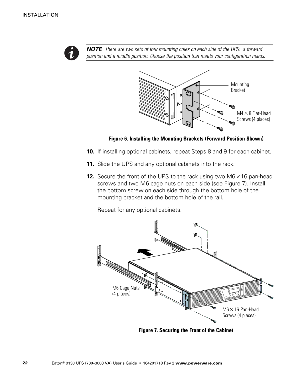
NOTE There are two sets of four mounting holes on each side of the UPS: a forward position and a middle position. Choose the position that meets your configuration needs.
Mounting
Bracket
M4 8
Screws (4 places)
Figure 6. Installing the Mounting Brackets (Forward Position Shown)
10.If installing optional cabinets, repeat Steps 8 and 9 for each cabinet.
11.Slide the UPS and any optional cabinets into the rack.
12. Secure the front of the UPS to the rack using two M6 16
Repeat for any optional cabinets.
M6 Cage Nuts (4 places)
M6 16
Screws (4 places)
Figure 7. Securing the Front of the Cabinet
22 | Eaton® 9130 UPS |