COMMUNICATION
When the communication cable is installed, power management software can exchange data with the UPS. The software polls the UPS for detailed information on the status of the power environment. If a power emergency occurs, the software initiates the saving of all data and an orderly shutdown of the equipment.
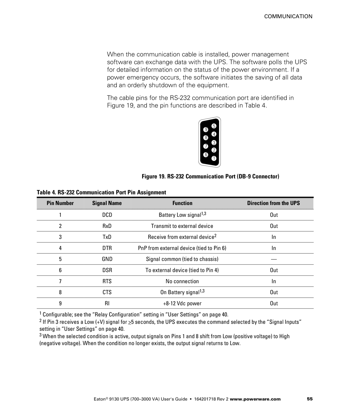
The cable pins for the
9
8
7
6
5
4
3
2
1
Figure 19. RS-232 Communication Port (DB-9 Connector)
Table 4. RS-232 Communication Port Pin Assignment
Pin Number | Signal Name | Function | Direction from the UPS |
|
|
|
|
1 | DCD | Battery Low signal1,3 | Out |
2 | RxD | Transmit to external device | Out |
|
|
|
|
3 | TxD | Receive from external device2 | In |
4 | DTR | PnP from external device (tied to Pin 6) | In |
|
|
|
|
5 | GND | Signal common (tied to chassis) | — |
|
|
|
|
6 | DSR | To external device (tied to Pin 4) | Out |
|
|
|
|
7 | RTS | No connection | In |
|
|
|
|
8 | CTS | On Battery signal1,3 | Out |
9 | RI | Out |
1Configurable; see the “Relay Configuration” setting in “User Settings” on page 40.
2If Pin 3 receives a Low (+V) signal for >5 seconds, the UPS executes the command selected by the “Signal Inputs” setting in “User Settings” on page 40.
3 When the selected condition is active, output signals on Pins 1 and 8 shift from Low (positive voltage) to High (negative voltage). When the condition no longer exists, the output signal returns to Low.
Eaton® 9130 UPS | 55 |