INSTALLATION
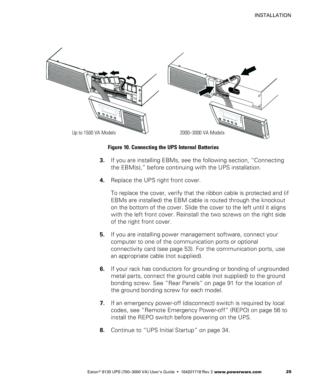
Up to 1500 VA Models |
Figure 10. Connecting the UPS Internal Batteries
3.If you are installing EBMs, see the following section, “Connecting the EBM(s),” before continuing with the UPS installation.
4.Replace the UPS right front cover.
To replace the cover, verify that the ribbon cable is protected and (if EBMs are installed) the EBM cable is routed through the knockout on the bottom of the cover. Slide the cover to the left until it aligns with the left front cover. Reinstall the two screws on the right side of the right front cover.
5.If you are installing power management software, connect your computer to one of the communication ports or optional connectivity card (see page 53). For the communication ports, use an appropriate cable (not supplied).
6.If your rack has conductors for grounding or bonding of ungrounded metal parts, connect the ground cable (not supplied) to the ground bonding screw. See “Rear Panels” on page 91 for the location of the ground bonding screw for each model.
7.If an emergency
8.Continue to “UPS Initial Startup” on page 34.
Eaton® 9130 UPS | 25 |