INSTALLATION
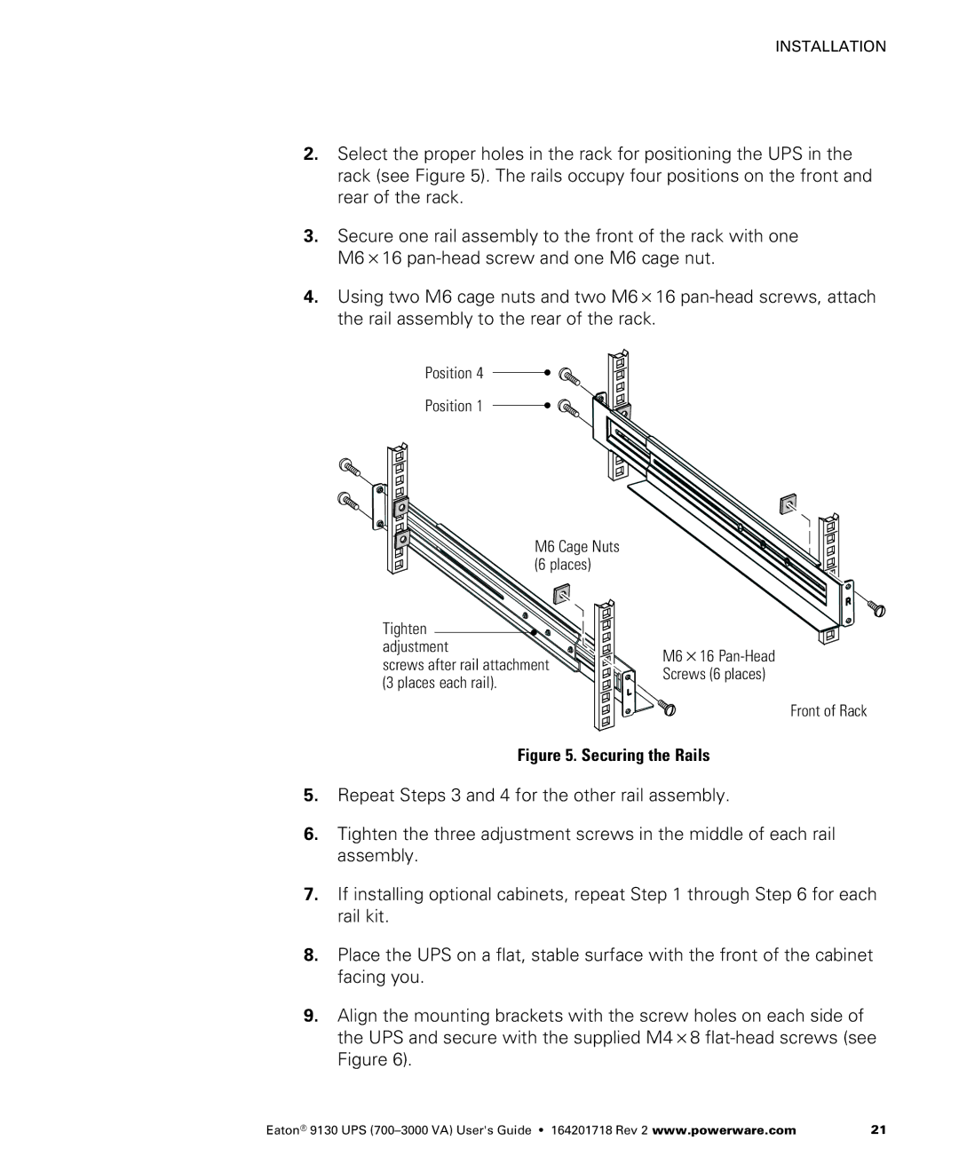
2.Select the proper holes in the rack for positioning the UPS in the rack (see Figure 5). The rails occupy four positions on the front and rear of the rack.
3.Secure one rail assembly to the front of the rack with one M6 16
4. Using two M6 cage nuts and two M6 16
Position 4
Position 1
M6 Cage Nuts (6 places)
Tighten |
| |
adjustment | M6 16 | |
screws after rail attachment | ||
Screws (6 places) | ||
(3 places each rail). | ||
|
Front of Rack
Figure 5. Securing the Rails
5.Repeat Steps 3 and 4 for the other rail assembly.
6.Tighten the three adjustment screws in the middle of each rail assembly.
7.If installing optional cabinets, repeat Step 1 through Step 6 for each rail kit.
8.Place the UPS on a flat, stable surface with the front of the cabinet facing you.
9.Align the mounting brackets with the screw holes on each side of
the UPS and secure with the supplied M4 8
Eaton® 9130 UPS | 21 |