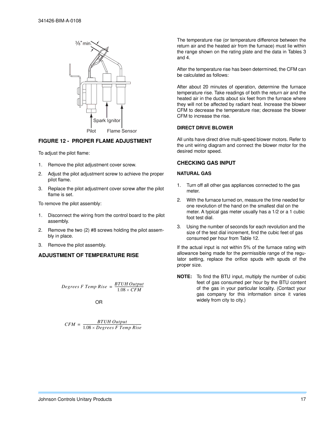
38" min.
Spark Ignitor
Pilot | Flame Sensor |
FIGURE 12 - PROPER FLAME ADJUSTMENT
To adjust the pilot flame:
1.Remove the pilot adjustment cover screw.
2.Adjust the pilot adjustment screw to achieve the proper pilot flame.
3.Replace the pilot adjustment cover screw after the pilot flame is set.
To remove the pilot assembly:
1.Disconnect the wiring from the control board to the pilot assembly.
2.Remove the two (2) #8 screws holding the pilot assem- bly in place.
3.Remove the pilot assembly.
ADJUSTMENT OF TEMPERATURE RISE
Degrees F Temp Rise = | |
| 1.08 ⋅ CFM |
| OR |
CFM = | BTUH Output |
The temperature rise (or temperature difference between the return air and the heated air from the furnace) must lie within the range shown on the rating plate and the data in Tables 3 and 4.
After the temperature rise has been determined, the CFM can be calculated as follows:
After about 20 minutes of operation, determine the furnace temperature rise. Take readings of both the return air and the heated air in the ducts about six feet from the furnace where they will not be affected by radiant heat. Increase the blower CFM to decrease the temperature rise; decrease the blower CFM to increase the rise.
DIRECT DRIVE BLOWER
All units have direct drive
CHECKING GAS INPUT
NATURAL GAS
1.Turn off all other gas appliances connected to the gas meter.
2.With the furnace turned on, measure the time needed for one revolution of the hand on the smallest dial on the meter. A typical gas meter usually has a 1/2 or a 1 cubic foot test dial.
3.Using the number of seconds for each revolution and the size of the test dial increment, find the cubic feet of gas consumed per hour from Table 12.
If the actual input is not within 5% of the furnace rating with allowance being made for the permissible range of the regu- lator setting, replace the orifice spuds with spuds of the proper size.
NOTE: To find the BTU input, multiply the number of cubic feet of gas consumed per hour by the BTU content of the gas in your particular locality. (Contact your gas company for this information since it varies widely from city to city.)
Johnson Controls Unitary Products | 17 |