GAS PIPING
Proper sizing of gas piping depends on the cubic feet per hour of gas flow required, specific gravity of the gas and the length of run. National Fuel Gas Code Z223.1 or CAN/CGA B149.1 or .2 should be followed in all cases unless super- seded by local codes or gas company requirements. Refer to Tables 5 and 6.
The heating value of the gas may differ with locality. The value should be checked with the local gas utility.
NOTE: There may be a local gas utility requirement specify- ing a minimum diameter for gas piping. All units require a 1/2 inch pipe connection at the gas valve.
GAS CONNECTION
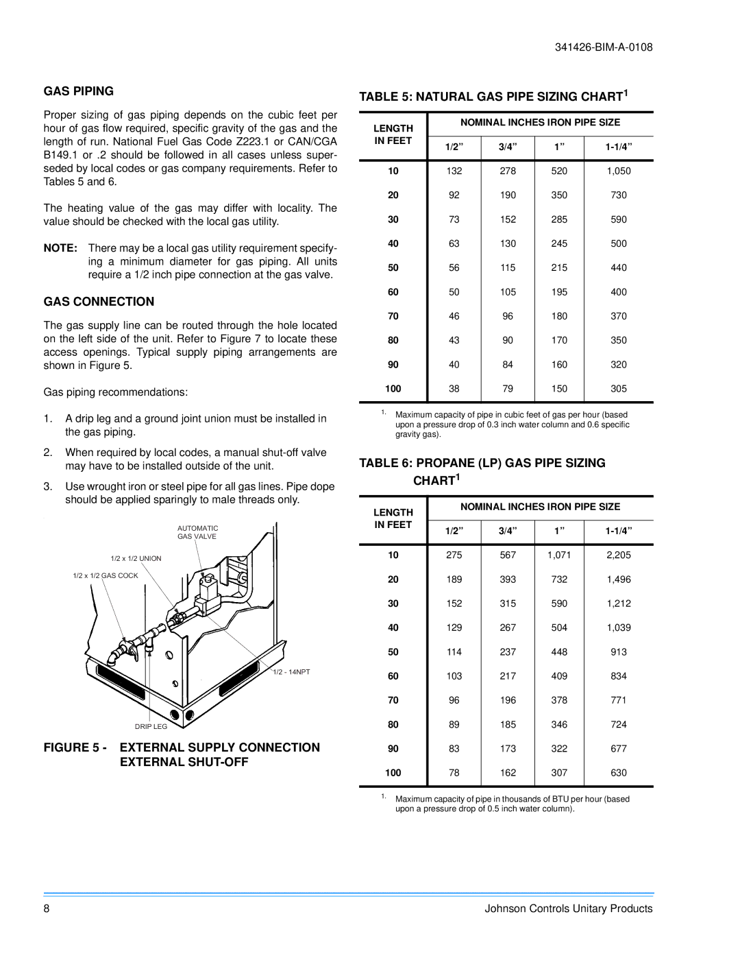
The gas supply line can be routed through the hole located on the left side of the unit. Refer to Figure 7 to locate these access openings. Typical supply piping arrangements are shown in Figure 5.
Gas piping recommendations:
1.A drip leg and a ground joint union must be installed in the gas piping.
2.When required by local codes, a manual
3.Use wrought iron or steel pipe for all gas lines. Pipe dope should be applied sparingly to male threads only.
.
AUTOMATIC
GASVALVE
1/2x1/2UNION
1/2x1/2GASCOCK
DRIPLEG
FIGURE 5 - EXTERNAL SUPPLY CONNECTION
EXTERNAL SHUT-OFF
TABLE 5: NATURAL GAS PIPE SIZING CHART1
LENGTH | NOMINAL INCHES IRON PIPE SIZE | ||||
|
|
|
| ||
IN FEET |
|
|
|
| |
1/2” | 3/4” | 1” | |||
| |||||
|
|
|
|
| |
10 | 132 | 278 | 520 | 1,050 | |
20 | 92 | 190 | 350 | 730 | |
30 | 73 | 152 | 285 | 590 | |
40 | 63 | 130 | 245 | 500 | |
50 | 56 | 115 | 215 | 440 | |
60 | 50 | 105 | 195 | 400 | |
70 | 46 | 96 | 180 | 370 | |
80 | 43 | 90 | 170 | 350 | |
90 | 40 | 84 | 160 | 320 | |
100 | 38 | 79 | 150 | 305 | |
|
|
|
|
| |
1.Maximum capacity of pipe in cubic feet of gas per hour (based upon a pressure drop of 0.3 inch water column and 0.6 specific gravity gas).
TABLE 6: PROPANE (LP) GAS PIPE SIZING CHART1
LENGTH | NOMINAL INCHES IRON PIPE SIZE | ||||
|
|
|
| ||
IN FEET |
|
|
|
| |
1/2” | 3/4” | 1” | |||
| |||||
|
|
|
|
| |
10 | 275 | 567 | 1,071 | 2,205 | |
20 | 189 | 393 | 732 | 1,496 | |
30 | 152 | 315 | 590 | 1,212 | |
40 | 129 | 267 | 504 | 1,039 | |
50 | 114 | 237 | 448 | 913 | |
60 | 103 | 217 | 409 | 834 | |
70 | 96 | 196 | 378 | 771 | |
80 | 89 | 185 | 346 | 724 | |
90 | 83 | 173 | 322 | 677 | |
100 | 78 | 162 | 307 | 630 | |
|
|
|
|
| |
1.Maximum capacity of pipe in thousands of BTU per hour (based upon a pressure drop of 0.5 inch water column).
8 | Johnson Controls Unitary Products |