2.Turn off all electric power to the appliance if service is to be performed.
3.Remove the control access panel.
4.Turn the gas valve switch to the OFF position. DO NOT FORCE.
5.Replace the control access panel.
POST-START CHECK LIST (GAS)
After the entire control circuit has been energized and the heating section is operating, make the following checks:
1.Check for gas leaks in the unit piping as well as the sup- ply piping.
2.Check for correct manifold gas pressures. See Checking Gas Input.
3.Check the supply gas pressure. It must be within the lim- its shown on rating nameplate. Supply pressure should be checked with all gas appliances in the building at full fire. At no time should the standby gas line pressure exceed 10.5", nor the operating pressure drop below 4.5" for natural gas units. If gas pressure is outside these limits, contact the local gas utility for corrective action.
MANIFOLD GAS PRESSURE ADJUSTMENT
Small adjustments to the gas flow may be made by turning the pressure regulator adjusting screw on the automatic gas valve. Refer to Figure 10.
|
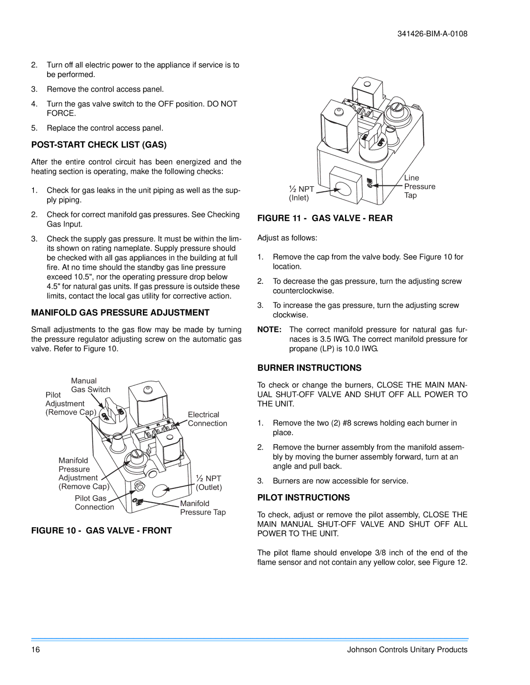
| Line |
½ NPT |
| Pressure |
| ||
(Inlet) |
| Tap |
|
|
FIGURE 11 - GAS VALVE - REAR
Adjust as follows:
1.Remove the cap from the valve body. See Figure 10 for location.
2.To decrease the gas pressure, turn the adjusting screw counterclockwise.
3.To increase the gas pressure, turn the adjusting screw clockwise.
NOTE: The correct manifold pressure for natural gas fur- naces is 3.5 IWG. The correct manifold pressure for propane (LP) is 10.0 IWG.
Manual |
| |
Pilot Gas Switch |
| |
Adjustment |
| |
(Remove Cap) | Electrical | |
| Connection | |
Manifold |
| |
Pressure | ½ NPT | |
Adjustment | ||
(Remove Cap) | (Outlet) | |
Pilot Gas | Manifold | |
Connection | ||
Pressure Tap | ||
|
FIGURE 10 - GAS VALVE - FRONT
BURNER INSTRUCTIONS
To check or change the burners, CLOSE THE MAIN MAN-
UAL SHUT-OFF VALVE AND SHUT OFF ALL POWER TO THE UNIT.
1.Remove the two (2) #8 screws holding each burner in place.
2.Remove the burner assembly from the manifold assem- bly by moving the burner assembly forward, turn at an angle and pull back.
3.Burners are now accessible for service.
PILOT INSTRUCTIONS
To check, adjust or remove the pilot assembly, CLOSE THE MAIN MANUAL
The pilot flame should envelope 3/8 inch of the end of the flame sensor and not contain any yellow color, see Figure 12.
16 | Johnson Controls Unitary Products |