AV-14FMG3/AV- 14FMG3B
Item |
| Measuring | Test point |
| Ad justment part |
| Description |
|
| |||||||||||
| instrument |
|
|
|
| |||||||||||||||
|
|
|
|
|
|
|
|
|
|
|
|
|
|
|
|
| ||||
|
|
|
|
|
|
|
|
|
|
|
|
|
|
|
|
|
|
|
|
|
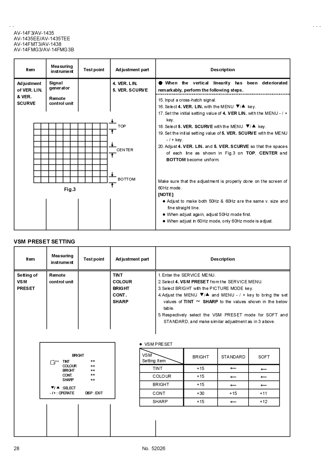
Ad justment |
| Signal |
|
|
|
|
|
|
| 4. VER. L IN. | ● When the | vertical linearity has | been | deteriorated | ||||||
of VER. LIN. |
| generator |
|
|
|
|
|
|
| 5. VER. SCURVE | remarkably, perform the following steps. |
|
| |||||||
|
|
|
|
|
|
|
|
|
|
|
|
|
| |||||||
& VER. |
| Remote |
|
|
|
|
|
|
|
|
| 15.Input a cross |
|
| ||||||
|
|
|
|
|
|
|
|
|
|
|
|
|
|
| ||||||
SCURVE |
| control unit |
|
|
|
|
|
|
|
|
|
|
| |||||||
|
|
|
|
|
|
|
|
|
| 16.Select 4. VER. LIN. with the MENU ▼/▲ key. |
| |||||||||
|
|
|
|
|
|
|
|
|
|
|
|
|
|
|
|
|
| |||
|
|
|
|
|
|
|
|
|
|
|
|
|
|
|
|
| 17.Set the initial setting value of 4. VER LIN. with the MENU | |||
|
|
|
|
|
|
|
|
|
|
|
|
|
|
|
|
| ||||
|
|
|
|
|
|
|
|
|
|
|
|
|
|
|
|
| key. |
|
|
|
|
|
|
|
|
|
|
|
|
|
|
|
|
|
|
|
|
|
|
| |
|
|
|
|
|
|
|
|
|
|
|
|
|
|
|
| TOP | 18.Select 5. VER. SCURVE with the MENU ▼/▲ key. | |||
|
|
|
|
|
|
|
|
|
|
|
|
|
|
|
| |||||
|
|
|
|
|
|
|
|
|
|
|
|
|
|
|
|
| 19.Set the initial setting value of 5. VER. SCURVE with the MENU | |||
|
|
|
|
|
|
|
|
|
|
|
|
|
|
|
|
| ||||
|
|
|
|
|
|
|
|
|
|
|
|
|
|
|
|
| ||||
|
|
|
|
|
|
|
|
|
|
|
|
|
|
|
|
|
|
|
| |
|
|
|
|
|
|
|
|
|
|
|
|
|
|
|
| CEN TER | 20.Adjust 4. VER. LIN. and 5. VER. SCURVE so that the spaces | |||
|
|
|
|
|
|
|
|
|
|
|
|
|
|
|
| |||||
|
|
|
|
|
|
|
|
|
|
|
|
|
|
|
| |||||
|
|
|
|
|
|
|
|
|
|
|
|
|
|
|
| |||||
|
|
|
|
|
|
|
|
|
|
|
|
|
|
|
| of each line | as shown in Fig.3 on | TOP, | CENTER and | |
|
|
|
|
|
|
|
|
|
|
|
|
|
|
|
|
| ||||
|
|
|
|
|
|
|
|
|
|
|
|
|
|
|
| BOTTOM | BOTTOM become uniform. |
|
| |
|
|
|
|
|
|
|
|
|
|
|
|
|
|
|
|
|
| |||
|
|
|
|
|
|
|
|
|
|
|
|
|
|
|
|
|
| |||
|
|
|
|
|
|
|
|
|
|
|
|
|
|
|
| Make sure that the adjustment is properly done on the screen of | ||||
|
|
|
|
|
|
|
|
|
|
|
|
|
|
|
| |||||
|
|
|
|
|
|
|
|
|
|
|
|
|
|
|
| |||||
|
|
|
|
|
|
|
|
|
|
|
|
|
|
|
| |||||
|
|
|
|
|
|
|
|
|
|
|
|
|
|
|
| |||||
|
|
|
|
|
|
|
|
|
|
|
|
|
|
|
| |||||
|
|
|
|
|
|
|
|
|
|
|
|
|
|
|
|
| ||||
|
|
|
|
|
| Fig.3 |
|
|
|
|
|
|
|
|
| 60Hz mode. |
|
|
| |
|
|
|
|
|
|
|
|
|
|
|
|
|
|
|
|
|
| |||
|
|
|
|
|
|
|
|
|
|
|
|
|
|
|
|
|
| |||
|
|
|
|
|
|
|
|
|
|
|
|
|
|
|
|
| [NOTE] |
|
|
|
|
|
|
|
|
|
|
|
|
|
|
|
|
|
|
|
| " Adjust to make both 50Hz & 60Hz are the same v. size and | |||
|
|
|
|
|
|
|
|
|
|
|
|
|
|
|
|
| ||||
|
|
|
|
|
|
|
|
|
|
|
|
|
|
|
|
| fine straight line. |
|
| |
|
|
|
|
|
|
|
|
|
|
|
|
|
|
|
|
| " When adjust again, adjust 50Hz mode first. |
| ||
|
|
|
|
|
|
|
|
|
|
|
|
|
|
|
|
| " When adjust in 60Hz mode, only 60Hz mode is adjust. | |||
|
|
|
|
|
|
|
|
|
|
|
|
|
|
|
|
|
|
|
|
|
VSM PRESET SETTING
Item
Measuring instrument
Test point
Ad justment part
Description
Setting of
VSM PRESET
Remote control unit
TINT COLOUR BRIGHT CONT .
SHARP
1.Enter the SERVICE MENU.
2.Select 4. VSM PRESET from the SERVICE MENU.
3.Select BRIGHT with the PICTURE MODE key.
4.Adjust the MENU ▼/▲ and MENU
5.Respectively select the VSM PRESET mode for SOFT and STANDARD, and make similar adjustment as in 3 above.
BRIGHT
TINT**
COLOUR **
BRIGHT **
CONT. **
SHARP **
/ | :SELECT |
|
DISP : EXIT | ||
•VSM PRESET
VSM | BRIGHT | STANDARD | SOFT | |
Setting Item | ||||
|
|
| ||
|
|
|
| |
TINT | +15 | ← | ← | |
COLOUR | +15 | ← | ← | |
BRIGHT | +15 | ← | ← | |
CONT | +30 | +15 | +11 | |
|
|
|
| |
SHARP | +15 | ← | +12 | |
|
|
|
|
28 | No. 52026 |