AV-14FMG3/AV- 14FMG3B
ADJUSTMENTS
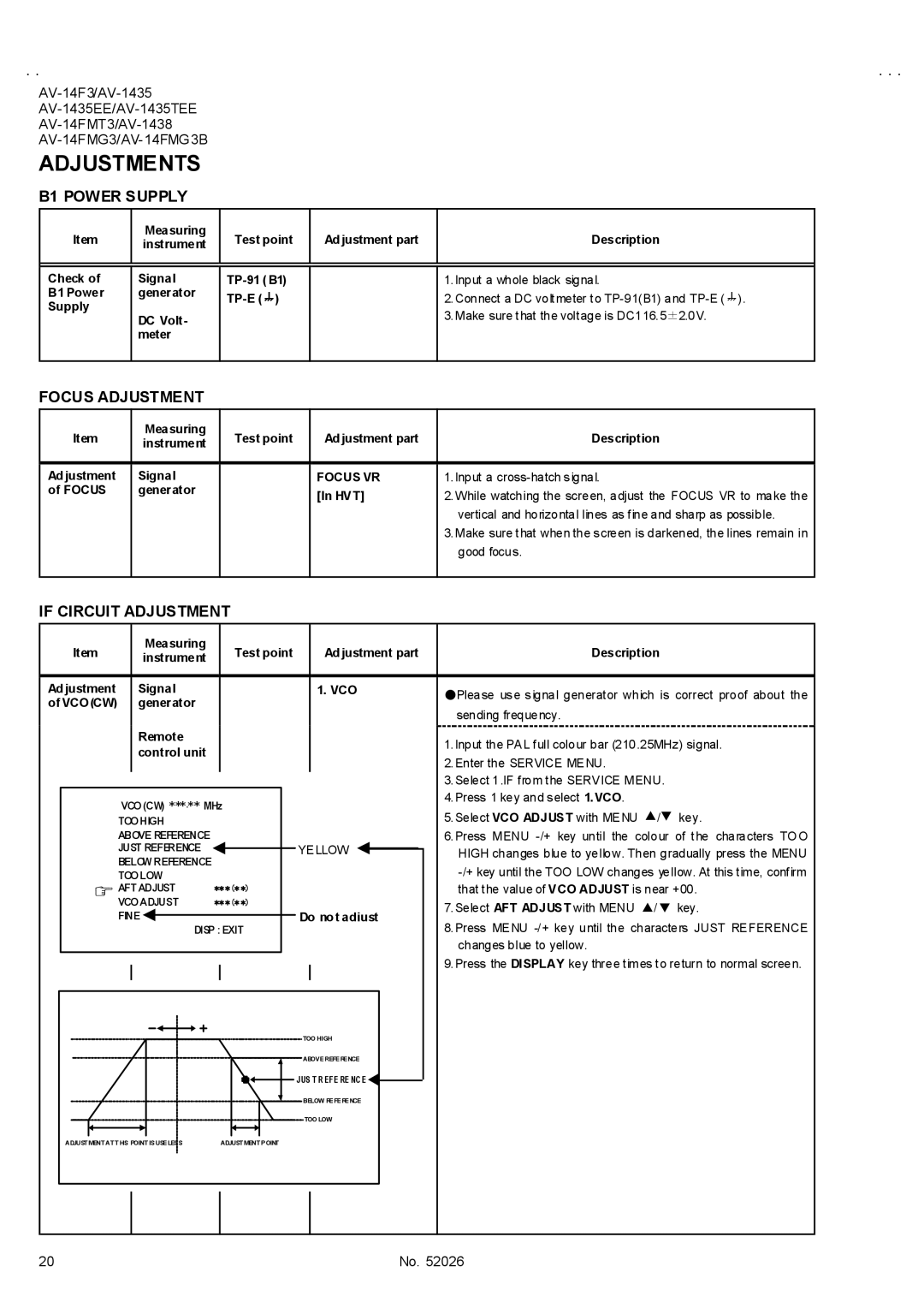
B1 POWER SUPPLY
Item | Measuring | Test point | Ad justment part | Description | |
instrument | |||||
|
|
|
| ||
|
|
|
|
| |
|
|
|
|
| |
Check of | Signal |
| 1.Input a whole black signal. | ||
B1 Power | generator |
| 2.Connect a DC voltmeter to | ||
Supply |
|
| |||
|
|
| 3.Make sure that the voltage is DC116.5±2.0V. | ||
| DC Volt- |
|
| ||
|
|
|
| ||
| meter |
|
|
| |
|
|
|
|
|
FOCUS ADJUSTMENT
Item | Measuring | Test point | Ad justment part | Description | |
instrument | |||||
|
|
|
| ||
|
|
|
|
| |
Ad justment | Signal |
| FOCUS VR | 1.Input a | |
of FOCUS | generator |
| [In HVT] | 2.While watching the screen, adjust the FOCUS VR to make the | |
|
|
| |||
|
|
|
| vertical and horizontal lines as fine and sharp as possible. | |
|
|
|
| 3.Make sure that when the screen is darkened, the lines remain in | |
|
|
|
| good focus. | |
|
|
|
|
|
IF CIRCUIT ADJUSTMENT
|
| Item |
| Measuring |
|
| Test point |
| Ad justment part | Description | ||||
|
|
| instrument |
|
|
| ||||||||
|
|
|
|
|
|
|
|
|
|
|
|
| ||
|
|
|
|
|
|
|
|
|
|
|
|
|
|
|
Ad justment |
| Signal |
|
|
|
|
|
| 1. VCO | ●Please use signal generator which is correct proof about the | ||||
of VCO(CW) |
| generator |
|
|
|
|
|
|
|
| ||||
|
|
|
|
|
|
|
|
| sending frequency. | |||||
|
|
|
|
|
|
|
|
|
|
|
|
|
| |
|
|
|
| Remote |
|
|
|
|
|
|
|
| 1.Input the PAL full colour bar (210.25MHz) signal. | |
|
|
|
| control unit |
|
|
|
|
|
|
|
| ||
|
|
|
|
|
|
|
|
|
|
|
| 2.Enter the SERVICE MENU. | ||
|
|
|
|
|
|
|
|
|
|
|
|
|
| |
|
|
|
|
|
|
|
|
|
|
|
|
|
| 3.Select 1.IF from the SERVICE MENU. |
|
|
|
|
|
|
|
|
|
|
|
|
|
| 4.Press 1 key and select 1.VCO. |
|
|
| VCO (CW) ***.** MHz |
|
|
|
|
| ||||||
|
|
|
|
|
|
|
| 5.Select VCO ADJUST with MENU ▲/▼ key. | ||||||
|
|
| TOO HIGH |
|
|
|
|
|
|
|
| |||
|
|
| ABOVE REFERENCE |
|
|
|
|
|
|
|
| 6.Press MENU | ||
|
|
| JUST REFERENCE |
|
|
|
|
|
|
|
|
| ||
|
|
|
|
|
|
|
| YELLOW | HIGH changes blue to yellow. Then gradually press the MENU | |||||
|
|
| BELOW REFERENCE |
|
|
|
|
| ||||||
|
|
|
|
|
|
|
|
|
|
| ||||
|
|
| TOO LOW |
|
|
|
|
|
|
|
| |||
|
|
| AFT ADJUST | ** *(* *) |
|
|
|
|
| that the value of VCO ADJUST is near +00. | ||||
|
|
| VCO ADJUST | ** *(* *) |
|
|
|
|
| 7.Select AFT ADJUST with MENU ▲/▼ key. | ||||
|
|
| FINE |
|
|
|
|
|
| Do no t adjust | ||||
|
|
| DISP : EXIT |
|
| 8.Press MENU | ||||||||
|
|
|
|
|
|
|
|
|
| |||||
|
|
|
|
|
|
|
|
|
|
|
|
|
| changes blue to yellow. |
|
|
|
|
|
|
|
|
|
|
|
|
|
| 9.Press the DISPLAY key three times to return to normal screen. |
|
|
|
|
|
|
|
|
|
|
|
|
|
| |
|
|
|
|
|
|
|
|
|
|
|
|
|
|
|
TOO HIGH
ABOVE REFERENCE
![]()
![]() JUS T R EFE RE NC E
JUS T R EFE RE NC E![]()
![]() BELOW REFERENCE
BELOW REFERENCE
TOO LOW
ADJUSTMENT AT THIS POINT IS USELESS | ADJUSTMENT POINT |
20 | No. 52026 |