English
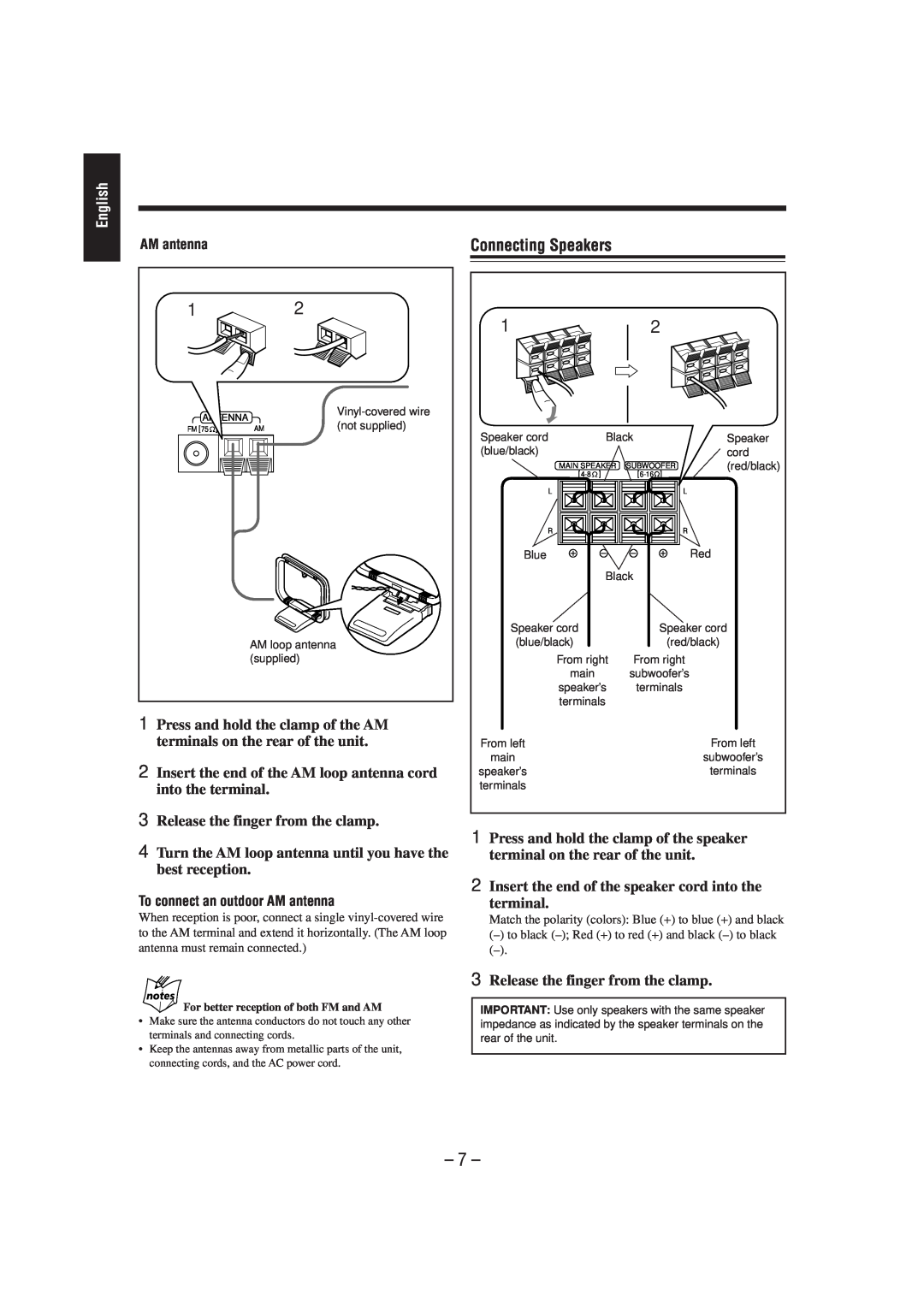
AM antenna
1 |
| 2 |
|
ANTENNA |
| ||
| (not supplied) | ||
FM [75 | ] | AM | |
|
| AM loop antenna |
|
|
| (supplied) |
|
1Press and hold the clamp of the AM terminals on the rear of the unit.
2Insert the end of the AM loop antenna cord into the terminal.
3Release the finger from the clamp.
4Turn the AM loop antenna until you have the best reception.
To connect an outdoor AM antenna
When reception is poor, connect a single
Connecting Speakers
1 |
| 2 |
|
Speaker cord | Black | Speaker | |
(blue/black) |
|
| cord |
MAIN SPEAKER | SUBWOOFER | (red/black) | |
[ | ] |
| |
L |
| L |
|
R |
| R |
|
Blue |
|
| Red |
| Black |
| |
Speaker cord |
| Speaker cord | |
(blue/black) |
| (red/black) | |
From right | From right |
| |
main |
| subwoofer’s |
|
speaker’s | terminals |
| |
terminals |
|
| |
From left |
|
| From left |
main |
|
| subwoofer’s |
speaker’s |
|
| terminals |
terminals |
|
|
|
1Press and hold the clamp of the speaker terminal on the rear of the unit.
2Insert the end of the speaker cord into the
terminal.
Match the polarity (colors): Blue (+) to blue (+) and black
(–)to black
For better reception of both FM and AM
•Make sure the antenna conductors do not touch any other terminals and connecting cords.
•Keep the antennas away from metallic parts of the unit, connecting cords, and the AC power cord.
3Release the finger from the clamp.
IMPORTANT: Use only speakers with the same speaker impedance as indicated by the speaker terminals on the rear of the unit.