The screen for audio channel selection disappears.
Using the audio level meter
You can check the conditions of the current EMBEDDED AUDIO signals in the audio level meter (“On the Information Display” on the right,“LEVEL METER SETTING” in “AUDIO SETTING” on page 14).
Press MENU button.
4
1 Press or button when a menu is not displayed.
The screen for audio channel selection is displayed.
• The screen for audio channel selection automatically disappears in about 30 seconds after the previous operation.
Audio channel selection screen
Selected item
2 Press buttons to select the left (L ch) or right (R ch).
3 Press buttons to select an audio channel.
• Each time you press the button, the audio channel changes according to the settings of “E.AUDIO GROUP” (“NOTE” on page 14).

Menu Operations

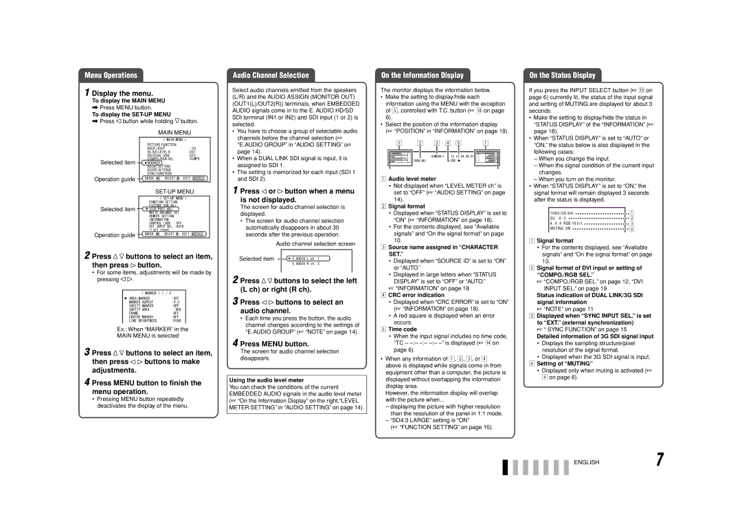
1 Display the menu.

To display the MAIN MENU

\Press MENU button.

To display the SET-UP MENU

\Press button while holding button.

MAIN MENU

Selected item

Operation guide

SET-UP MENU

Selected item

Operation guide

2 Press buttons to select an item, then press button.

For some items, adjustments will be made by

pressing .

Ex.: When “MARKER” in the

MAIN MENU is selected

3 Press buttons to select an item,

then press buttons to make adjustments.

4 Press MENU button to finish the menu operation.

Pressing MENU button repeatedly deactivates the display of the menu.

Audio Channel Selection

Select audio channels emitted from the speakers (L/R) and the AUDIO ASSIGN (MONITOR OUT) (OUT1(L)/OUT2(R)) terminals, when EMBEDDED AUDIO signals come in to the E. AUDIO HD/SD SDI terminal (IN1 or IN2) and SDI input (1 or 2) is selected.

You have to choose a group of selectable audio channels before the channel selection (“E.AUDIO GROUP” in “AUDIO SETTING” on page 14).

When a DUAL LINK SDI signal is input, it is assigned to SDI 1.

The setting is memorized for each input (SDI 1 and SDI 2).

On the Information Display

The monitor displays the information below.

Make the setting to display/hide each information using the MENU with the exception of 5, controlled with T.C. button (r on page 6).

Select the position of the information display

(“POSITION” in “INFORMATION” on page 18).

1Audio level meter

Not displayed when “LEVEL METER ch” is set to “OFF” (“AUDIO SETTING” on page 14).

2Signal format

Displayed when “STATUS DISPLAY” is set to “ON” (“INFORMATION” on page 18).

For the contents displayed, see “Available signals” and “On the signal format” on page 10.

3Source name assigned in “CHARACTER SET.”

Displayed when “SOURCE ID” is set to “ON” or “AUTO.”

Displayed in large letters when “STATUS DISPLAY” is set to “OFF” or “AUTO.”

“INFORMATION” on page 18

4 CRC error indication

• Displayed when “CRC ERROR” is set to “ON” (“INFORMATION” on page 18).

• A red square is displayed when an error occurs.

5 Time code

• When the input signal includes no time code, “TC – –:– –:– –:– –” is displayed (r on page 6).

When any information of 1, 2, 3, or 4 above is displayed while signals come in from equipment other than a computer, the picture is displayed without overlapping the information display area.

However, the information display will overlap with the picture when...

displaying the picture with higher resolution than the resolution of the panel in 1:1 mode.

“SD4:3 LARGE” setting is “ON”

(“FUNCTION SETTING” on page 16).

On the Status Display

If you press the INPUT SELECT button (t on page 6) currently lit, the status of the input signal and setting of MUTING are displayed for about 3 seconds.

Make the setting to display/hide the status in “STATUS DISPLAY” of the “INFORMATION” (page 18).

When “STATUS DISPLAY” is set to “AUTO” or “ON,” the status below is also displayed in the following cases:

When you change the input.

When the signal condition of the current input changes.

When you turn on the monitor.

When “STATUS DISPLAY” is set to “ON,” the signal format will remain displayed 3 seconds after the status is displayed.

1Signal format

For the contents displayed, see “Available signals” and “On the signal format” on page 10.

2Signal format of DVI input or setting of “COMPO./RGB SEL.”

“COMPO./RGB SEL.” on page 12, “DVI

INPUT SEL.” on page 19

Status indication of DUAL LINK/3G SDI signal information

“NOTE” on page 11

3Displayed when “SYNC INPUT SEL.” is set to “EXT.” (external synchronization)

“ SYNC FUNCTION” on page 15

Detailed information of 3G SDI signal input

Displays the sampling structure/pixel resolution of the signal format.

Displayed when the 3G SDI signal is input.

4 Setting of “MUTING”

Displayed only when muting is activated (4 on page 6).

ENGLISH7

Page 7
Image 7
JVC DT-V20L3G, DT-V24G1, 0110SKH-MW-MT specifications Display the menu, Press buttons to select an item, then press button

DT-V20L3G, 0110SKH-MW-MT, DT-V24G1 specifications

The JVC DT-V24G1 is a versatile 24-inch broadcast monitor designed for high-end professional applications. This monitor stands out with its full HD resolution of 1920 x 1200 pixels, ensuring that content is displayed with exceptional clarity and detail. Its advanced 10-bit IPS panel provides wide viewing angles, allowing multiple viewers to see the same high-quality image without color distortion. The DT-V24G1 supports various input formats, including SDI, HDMI, and composite, making it compatible with a wide range of video sources.

Another significant feature is the integrated waveform and vectorscope, which assist in professional monitoring and ensure accurate color grading and signal integrity. The DT-V24G1 is also equipped with built-in audio level meters, providing straightforward audio monitoring during production processes. Its flexible mount options add to its utility, allowing for easy integration into any studio setup or mobile broadcast unit.

The JVC DT-V20L3G is another noteworthy model, offering a 20-inch LCD display that delivers stunning picture quality with a native resolution of 1920 x 1080 pixels. This model is particularly suited for applications where space is at a premium, without sacrificing performance. It includes advanced color management tools, which allow for precise control over color reproduction, making it ideal for critical color work in post-production environments.

The DT-V20L3G features multiple input options, including HDMI, SDI, and DisplayPort, ensuring versatility and flexibility across various media types. It also has a compact and lightweight design, facilitating ease of transport for location shoots and smaller studio setups. The monitor’s built-in calibration tools allow users to maintain accurate color settings, ensuring reliability in every viewing condition.

Together, these monitors represent JVC's commitment to providing high-performance, reliable solutions for broadcast professionals. With advanced features, robust technologies, and a focus on user-friendly design, the JVC DT-V24G1 and DT-V20L3G are perfect for those looking to elevate their production quality. Whether in a studio, on location, or during post-production, these monitors stand out as essential tools for any broadcasting setup.