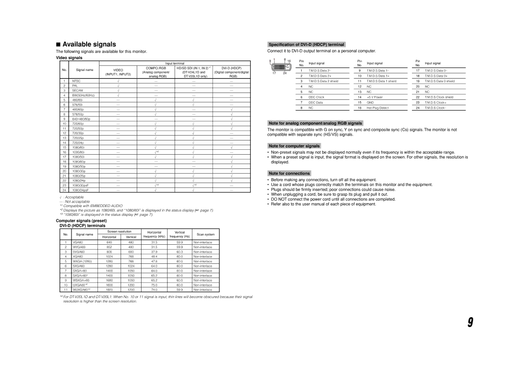
7Available signals
The following signals are available for this monitor.
Video signals
|
|
| Input terminal |
| ||
No. | Signal name | VIDEO | COMPO./RGB | HD/SD SDI (IN 1, IN 2)*1 | ||
(Analog component/ | (Digital component/digital | |||||
|
| (INPUT1, INPUT2) | ||||
|
| analog RGB) | RGB) | |||
|
|
| ||||
1 | NTSC | √ | — | — | — | |
2 | PAL | √ | — | — | — | |
3 | SECAM | √ | — | — | — | |
4 | BW(50Hz/60Hz) | √ | — | — | — | |
5 | 480/60i | — | √ | √ | — | |
6 | 576/50i | — | √ | √ | — | |
7 | 480/60p | — | √ | — | √ | |
8 | 576/50p | — | √ | — | √ | |
9 | 640∗480/60p | — | — | — | √ | |
10 | 720/60p | — | √ | √ | √ | |
11 | 720/50p | — | √ | √ | √ | |
12 | 720/30p | — | √ | √ | — | |
13 | 720/25p | — | √ | √ | — | |
14 | 720/24p | — | √ | √ | — | |
15 | 1080/60i | — | √ | √ | √ | |
16 | 1035/60i | — | √*2 | √ | — | |
17 | 1080/50i | — | √ | √ | √ | |
18 | 1080/60p | — | — | — | √ | |
19 | 1080/50p | — | — | — | √ | |
20 | 1080/30p | — | √ | √ | √ | |
21 | 1080/25p | — | √ | √ | √ | |
22 | 1080/24p | — | √ | √ | √ | |
23 | 1080/30psF | — | √*3 | √*3 | — | |
24 | 1080/24psF | — | √ | √ | — | |
√: Acceptable
—: Not acceptable
*1 Compatible with EMBEDDED AUDIO
*2 Displays the picture as 1080/60i, and “1080/60i” is displayed in the status display (☞ page 7). *3 “1080/60i” is displayed in the status display (☞ page 7).
Computer signals (preset)
DVI-D (HDCP) terminals
No. | Signal name | Screen resolution | Horizontal | Vertical | Scan system | ||
Horizontal | Vertical | frequency (kHz) | frequency (Hz) | ||||
|
|
| |||||
|
|
|
|
|
|
| |
1 | VGA60 | 640 | 480 | 31.5 | 59.9 | ||
2 | WVGA60 | 852 | 480 | 31.5 | 59.9 | ||
3 | SVGA60 | 800 | 600 | 37.9 | 60.3 | ||
4 | XGA60 | 1024 | 768 | 48.4 | 60.0 | ||
5 | WXGA (1280) | 1280 | 768 | 47.8 | 60.0 | ||
6 | SXGA60 | 1280 | 1024 | 64.0 | 60.0 | ||
7 | SXGA+60 | 1400 | 1050 | 64.0 | 60.0 | ||
8 | SXGA+60* | 1400 | 1050 | 65.2 | 60.0 | ||
9 | WSXGA+60 | 1680 | 1050 | 65.2 | 60.0 | ||
10 | UXGA60*4 | 1600 | 1200 | 75.0 | 60.0 | ||
11 | WUXGA60*4 | 1920 | 1200 | 74.0 | 59.9 | ||
*4 For
Specification of DVI-D (HDCP) terminal
Connect it to DVI-D output terminal on a personal computer.
Pin | Input signal |
| Pin | Input signal |
| Pin | Input signal |
No. |
| No. |
| No. | |||
|
|
|
|
| |||
1 | T.M.D.S Data 2– |
| 9 | T.M.D.S Data 1– |
| 17 | T.M.D.S Data 0– |
2 | T.M.D.S Data 2+ |
| 10 | T.M.D.S Data 1+ |
| 18 | T.M.D.S Data 0+ |
3 | T.M.D.S Data 2 shield | 11 | T.M.D.S Data 1 shield | 19 | T.M.D.S Data 0 shield | ||
|
|
|
|
|
|
|
|
4 | NC | 12 | NC | 20 | NC | ||
|
|
|
|
|
|
|
|
5 | NC | 13 | NC | 21 | NC | ||
|
|
|
|
|
|
|
|
6 | DDC Clock | 14 | +5 V Power | 22 | T.M.D.S Clock shield | ||
|
|
|
|
|
|
|
|
7 | DDC Data | 15 | GND | 23 | T.M.D.S Clock+ | ||
|
|
|
|
|
|
|
|
8 | NC |
| 16 | Hot Plug Detect |
| 24 | T.M.D.S Clock– |
Note for analog component/analog RGB signals
The monitor is compatible with G on sync, Y on sync and composite sync (Cs) signals. The monitor is not compatible with separate sync (HS/VS) signals.
Note for computer signals
•
•When a preset signal is input, the signal format is displayed on the screen. For other signals, the resolution is displayed.
Note for connections
•Before making any connections, turn off all the equipment.
•Use a cord whose plugs correctly match the terminals on this monitor and the equipment.
•Plugs should be firmly inserted; poor connections could cause noise.
•When unplugging a cord, be sure to grasp its plug and pull it out.
•DO NOT connect the power cord until all connections are completed.
•Refer also to the user manual of each piece of equipment.
9