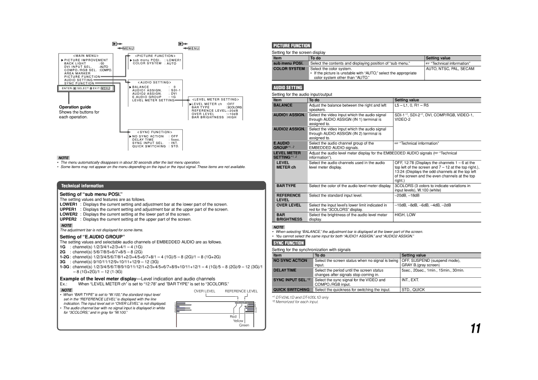
Operation guide Shows the buttons for each operation.
NOTE
•The menu automatically disappears in about 30 seconds after the last menu operation.
•Some items may not appear on the menu depending on the input or the input signal. These items are not available.
Technical information
Setting of “sub menu POSI.”
The setting values and features are as follows.
LOWER1 : Displays the current setting and adjustment bar at the lower part of the screen.
UPPER1 : Displays the current setting and adjustment bar at the upper part of the screen.
LOWER2 : Displays the current setting at the lower part of the screen.
UPPER2 : Displays the current setting at the upper part of the screen.
NOTE
The adjustment bar is not displayed for some items.
Setting of “E.AUDIO GROUP”
The setting values and selectable audio channels of EMBEDDED AUDIO are as follows.
1G : channel(s) 1/2/3/4/1+2/3+4/1 – 4 (1G)
2G : channel(s) 5/6/7/8/5+6/7+8/5 – 8 (2G)
3G : channel(s) 9/10/11/12/9+10/11+12/9 – 12 (3G)
– 8 (1G+2G)/1 – 12
Example of the level meter
Ex.: | When “LEVEL METER ch” is set to “12:78” and ”BAR TYPE” is set to “3COLORS.” |
PICTURE FUNCTION
Setting for the screen display
Item | To do | Setting value |
sub menu POSI. | Select the contents and displaying position of “sub menu.” | ☞ “Technical information” |
COLOR SYSTEM | Select the color system. | AUTO, NTSC, PAL, SECAM |
| • If the picture is unstable with “AUTO,” select the appropriate |
|
| color system other than “AUTO.” |
|
AUDIO SETTING
Setting for the audio input/output
Item | To do | Setting value | |
BALANCE | Adjust the balance between the right and left | L5 – L1, 0, R1 – R5 | |
|
| speakers. |
|
AUDIO1 ASSIGN. | Select the video input which the audio signal | ||
|
| through AUDIO ASSIGN (IN 1) terminal is | |
|
| assigned to. |
|
AUDIO2 ASSIGN. | Select the video input which the audio signal |
| |
|
| through AUDIO ASSIGN (IN 2) terminal is |
|
|
| assigned to. |
|
E.AUDIO | Select the audio channel group of the | ☞ “Technical information” | |
GROUP*1, 2 | EMBEDDED AUDIO signals. |
| |
LEVEL METER | Adjust the audio level meter display for the EMBEDDED AUDIO signals (☞ “Technical | ||
SETTING*1, 2 | information”). |
| |
| LEVEL | Select the audio channels used in the audio | OFF, 12:78 (Displays the channels 1 – 6 at the |
| METER ch | level meter display. | top left of the screen and 7 – 12 at the top right.), |
|
|
| 13:24 (Displays the odd channels at the top left |
|
|
| of the screen and the even channels at the top |
|
|
| right.) |
| BAR TYPE | Select the color of the audio level meter display. | 3COLORS (3 colors to indicate variations in |
|
|
| input levels), W.100 (white) |
| REFERENCE | Select the standard input level. | |
| LEVEL |
|
|
| OVER LEVEL | Select the input level’s lower limit indicated in | |
|
| red for the “3COLORS” display. |
|
| BAR | Select the brightness of the audio level meter | HIGH, LOW |
| BRIGHTNESS | display. |
|
NOTE
•When selecting “BALANCE,” the adjustment bar is displayed at the lower part of the screen.
•You cannot select the same input for both “AUDIO1 ASSIGN.” and “AUDIO2 ASSIGN.”
SYNC FUNCTION
Setting for the synchronization with signals
Item | To do | Setting value |
NO SYNC ACTION | Select the screen status when no signal is being | OFF, SUSPEND (suspend mode), |
| input. | GRAY B.(gray screen) |
DELAY TIME | Select the period until the screen status | 5sec., 20sec., 1min., 15min., 30min. |
| changes after signals stop coming in. |
|
SYNC INPUT SEL.*2 | Select the sync signal for the VIDEO and | INT., EXT. |
| COMPO./RGB input. |
|
NOTE
•When “BAR TYPE” is set to “W.100,” the standard input level set in the “REFERENCE LEVEL” is displayed with the line indication. The input level set in “OVER LEVEL” is not displayed.
•The audio channel bar with no signal input is displayed in white for “3COLORS,” and in gray for “W.100.”
OVER LEVEL | REFERENCE LEVEL | |||||||||
|
|
|
|
|
|
|
|
|
|
|
|
|
|
|
|
|
|
|
|
|
|
|
|
|
|
|
|
|
|
|
|
|
|
|
|
|
|
|
|
|
|
|
|
|
|
|
|
|
|
|
|
|
|
|
|
|
|
|
|
|
|
|
|
|
|
Red
Yellow
Green
QUICK SWITCHING Select the quickness for switching the input. | STD., QUICK |
*1
11