Category | Menu item |
| Selectable setting, [Initial: Underlined] |
| SSM *2 | • SSM 01 – 06 | : For settings, see “Automatic presetting |
|
| • SSM 07 – 12 | station Sequential Memory)” on page 2. |
|
| • SSM 13 – 18 |
|
| AREA | • AREA US | : When using in North/Central/South America. AM/FM |
|
| • AREA EU | intervals are set to 10 kHz/200 kHz. |
|
| : When using in any other areas. AM/FM intervals are set to | |
|
| • AREA SA | 9 kHz/50 kHz (100 kHz during auto search). |
TUNER |
| : When using in South American countries where FM interval | |
|
| is 100 kHz. AM interval is set to 10 kHz. | |
MONO *2 | • MONO ON | : Activate monaural mode to improve FM reception, but | |
|
|
| stereo effect will be lost. |
|
| • MONO OFF | : Restore the stereo effect. |
| IF BAND | • AUTO | : Increases the tuner selectivity to reduce interference noises |
|
| • WIDE | between adjacent stations. (Stereo effect may be lost.) |
|
| : Subject to interference noises from adjacent stations, but | |
|
|
| sound quality will not be degraded and the stereo effect will |
|
|
| remain. |
| FADER *3 | R06 – F06 [ 00 ] | : Adjust the front and rear speaker output balance. |
| BALANCE *4 | L06 – R06 [ 00 ] | : Adjust the left and right speaker output balance. |
| LOUD | • LOUD ON | : Boost low and high frequencies to produce a |
|
|
| sound at a low volume level. |
|
| • LOUD OFF | : Cancels. |
| AUX | AUX ADJ 00 — | : Adjust the auxiliary input level to avoid the sudden increase |
| ADJUST *5 | AUX ADJ 05 | of the output level when changing the source to the external |
|
|
| component connected to the AUX input jack on the control |
|
|
| panel. |
| L/O MODE | • SUB.W | : Select if the REAR LINE OUT terminals are used for |
|
|
| connecting a subwoofer (through an external amplifier). |
|
| • REAR | : Select if the REAR LINE OUT terminals are used for |
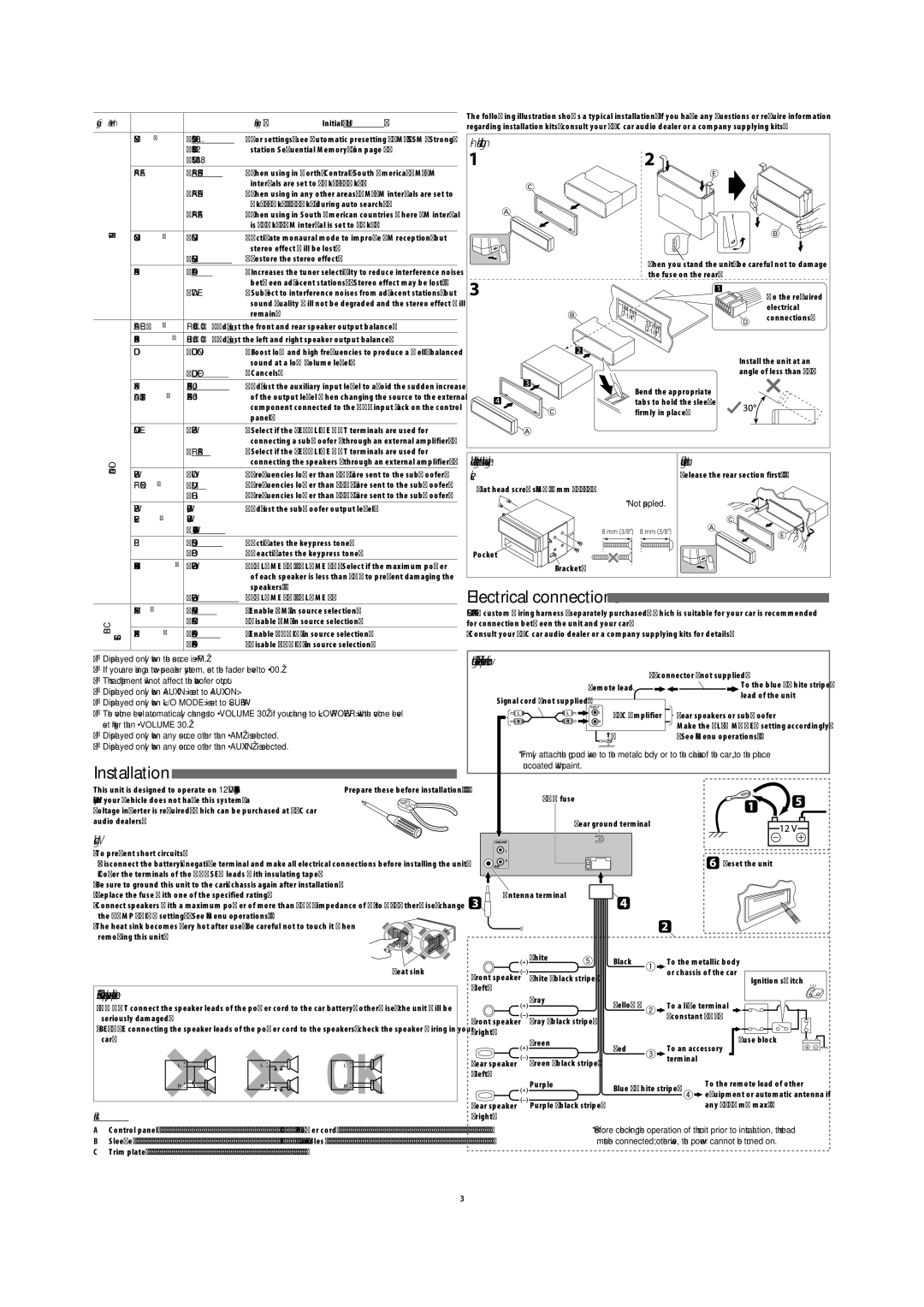
The following illustration shows a typical installation. If you have any questions or require information regarding installation kits, consult your JVC car audio dealer or a company supplying kits.
In-dash mounting
When you stand the unit, be careful not to damage the fuse on the rear.
![]()
![]()
![]() Do the required
Do the required
electrical connections.
Install the unit at an angle of less than 30˚.
Bend the appropriate tabs to hold the sleeve firmly in place.
AUDIO |
|
| connecting the speakers (through an external amplifier). | |
SUB.W | • LOW | : Frequencies lower than 72 Hz are sent to the subwoofer. | ||
| ||||
| FREQ *6 | • MID | : Frequencies lower than 111 Hz are sent to the subwoofer. | |
|
| • HIGH | : Frequencies lower than 157 Hz are sent to the subwoofer. | |
| SUB.W | SUB.W 00 — | : Adjust the subwoofer output level. | |
| LEVEL *6 | SUB.W 08 |
| |
|
| [ SUB.W 04 ] |
| |
| BEEP | • BEEP ON | : Activates the keypress tone. | |
|
| • BEEP OFF | : Deactivates the keypress tone. | |
| AMP GAIN *7 | • LOW POWER | : VOLUME 00 – VOLUME 30 (Select if the maximum power | |
|
|
| of each speaker is less than 50 W to prevent damaging the | |
|
|
| speakers.) |
When installing the unit without using the sleeve
Flat head
* Not supplied.
Bracket*
Removing the unit
Release the rear section first...
|
| • HIGH POWER | : VOLUME 00 – VOLUME 50 |
SRC SELECT | AM *8 | • AM ON | : Enable “AM” in source selection. |
| • AM OFF | : Disable “AM” in source selection. | |
AUX IN *9 | • AUX ON | : Enable “AUX IN” in source selection. | |
| • AUX OFF | : Disable “AUX IN” in source selection. | |
|
|
*2 Displayed only when the source is “FM.”
*3 If you are using a
*5 Displayed only when <AUX IN> is set to <AUX ON>. *6 Displayed only when <L/O MODE> is set to <SUB.W>.
*7 The volume level automatically changes to “VOLUME 30” if you change to <LOW POWER> with the volume level set higher than “VOLUME 30.”
*8 Displayed only when any source other than “AM” is selected.
*9 Displayed only when any source other than “AUX IN” is selected.
Installation 
This unit is designed to operate on 12 V DC, NEGATIVE ground | Prepare these before installation.... |
electrical systems. If your vehicle does not have this system, a |
|
voltage inverter is required, which can be purchased at JVC car |
|
audio dealers. |
|
Warnings
•To prevent short circuits:
•Be sure to ground this unit to the car’s chassis again after installation.
•Replace the fuse with one of the specified rating.
•Connect speakers with a maximum power of more than 50 W (impedance of 4 Ω to 8 Ω). Otherwise, change the <AMP GAIN> setting. (See “Menu operations.”)
•The heat sink becomes very hot after use. Be careful not to touch it when![]()
removing this unit.![]()
![]()
![]()
![]()
![]()
Heat sink
PRECAUTIONS on power supply and speaker connections
•DO NOT connect the speaker leads of the power cord to the car battery; otherwise, the unit will be seriously damaged.
•BEFORE connecting the speaker leads of the power cord to the speakers, check the speaker wiring in your car.
Parts List
A Control panel | 1 | D Power cord | 1 |
B Sleeve | 1 | E Handles | 2 |
C Trim plate | 1 |
|
|
Electrical connections 
IMPORTANT: A custom wiring harness (separately purchased) which is suitable for your car is recommended for connection between the unit and your car.
• Consult your JVC car audio dealer or a company supplying kits for details.
Connecting the external amplifier or subwoofer
Remote lead | To the blue (white stripe) | |
lead of the unit | ||
Signal cord (not supplied) | ||
| ||
JVC Amplifier | Rear speakers or subwoofer | |
| Make the <L/O MODE> setting accordingly. | |
* | (See “Menu operations.”) |
*Firmly attach the ground wire to the metallic body or to the chassis of the
15 A fuse
Rear ground terminal
![]() Reset the unit
Reset the unit
Antenna terminal
| White | Black | To the metallic body | |
|
| |||
Front speaker | White (black stripe) |
| or chassis of the car | |
|
| Ignition switch | ||
(left) |
|
|
|
|
| Gray | Yellow* | To a live terminal | |
|
| |||
Front speaker | Gray (black stripe) |
| (constant 12 V) | |
|
|
| ||
(right) |
|
|
| Fuse block |
| Green |
|
| |
| Red | To an accessory | ||
|
| |||
Rear speaker | Green (black stripe) |
| terminal |
|
|
|
| ||
(left) |
|
|
| To the remote lead of other |
| Purple | Blue (white stripe) | ||
|
| equipment or automatic antenna if | ||
|
|
|
| |
Rear speaker | Purple (black stripe) |
|
| any (200 mA max.) |
(right) |
|
|
|
|
*Before checking the operation of this unit prior to installation, this lead must be connected; otherwise, the power cannot be turned on.
3