6![]()
![]()
![]() EN
EN![]()
![]()
![]()
![]()
![]()
![]()
![]()
![]()
![]()
![]()
![]()
![]()
![]()
![]()
![]()
![]()
![]()
![]()
![]()
![]()
![]()
![]()
![]()
![]()
![]()
![]()
![]()
![]()
![]()
![]()
![]()
![]()
![]()
![]()
![]()
![]()
![]()
![]()
![]()
![]()
![]()
![]()
![]()
![]()
![]()
![]()
![]()
![]()
![]()
![]()
![]()
![]()
![]()
![]() IN
IN![]()
![]() STALLING YOUR
STALLING YOUR![]() NEW
NEW![]()
![]() VCR
VCR![]()
![]()
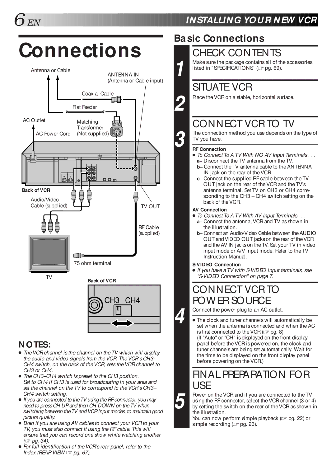
Connections
Antenna or Cable
ANTENNA IN
(Antenna or Cable input)
| Coaxial Cable |
| Flat Feeder |
AC Outlet | Matching |
| Transformer |
AC Power Cord | (Not supplied) |
Back of VCR |
|
Audio/Video |
|
Cable (supplied) | TV OUT |
| RF Cable |
| (supplied) |
| 75 ohm terminal |
TV | Back of VCR |
|
 CH3 CH4
NOTES:
●The VCR channel is the channel on the TV which will display the audio and video signals from the VCR. The VCR's CH3- CH4 switch, on the back of the VCR, sets the VCR channel to CH3 or CH4.
●The
Set to CH4 if CH3 is used for broadcasting in your area and set the channel on the TV to correspond to the VCR's CH3– CH4 switch setting.
●If you are connected to the TV using the RF connector, you may need to press CH UP and then CH DOWN on the TV when switching between the TV and VCR input modes, to maintain good picture quality.
●Even if you are using AV cables to connect your VCR to your TV, you must also connect it using the RF cable. This will ensure that you can record one show while watching another (☞ pg. 34).
●For full identification of the VCR's rear panel, refer to the Index (REAR VIEW ☞ pg. 67).
Basic Connections
| CHECK CONTENTS |
| Make sure the package contains all of the accessories |
1 listed in “SPECIFICATIONS” (☞ pg. 69). | |
| SITUATE VCR |
2 Place the VCR on a stable, horizontal surface. | |
3 | CONNECT VCR TO TV |
The connection method you use depends on the type of | |
TV you have. | |
| |
RF Connection | |
| ● To Connect To A TV With NO AV Input Terminals . . . |
| a– Disconnect the TV antenna from the TV. |
| b– Connect the TV antenna cable to the ANTENNA |
| IN jack on the rear of the VCR. |
| c– Connect the supplied RF cable between the TV |
| OUT jack on the rear of the VCR and the TV’s |
| antenna terminal. Set TV on CH3 or CH4 corre- |
| sponding to the CH3 – CH4 switch setting on the |
| back of the VCR. |
AV Connection
●To Connect To A TV With AV Input Terminals . . .
a– Connect the antenna, VCR and TV as shown in the illustration.
b– Connect an Audio/Video Cable between the AUDIO OUT and VIDEO OUT jacks on the rear of the VCR and the AV IN jacks on the TV. Set your TV in video input mode or A/V input mode. Refer to the TV Instruction Manual.
●If you have a TV with
| CONNECT VCR TO |
4 | POWER SOURCE |
Connect the power plug to an AC outlet. | |
| |
● The clock and tuner channels will automatically be | |
set when the antenna is connected and when the AC | |
| is first connected to the VCR (☞ pg. 8). |
| (If "Auto" or "CH" is displayed on the front display |
| panel before the VCR is powered on, the clock and |
| tuner channels are being set automatically. Wait for |
| the time to be displayed on the front display panel |
| before powering on the VCR.) |
|
|
| FINAL PREPARATION FOR |
| USE |
| Power on the VCR and if you are connected to the TV |
| using the RF connector, select the VCR channel (3 or 4) |
5 by setting the switch on the rear of the VCR as shown in | |
| the illustration. |
| You can now perform simple playback (☞ pg. 22) or |
| simple recording (☞ pg. 23). |