KS-FX725R
Contents
Safety precaution
Removing the front chassis assembly See
Disassembly method
Main body Removing the front panel assembly See
Removing the bottom cover See
Removing the heat sink See
Removing the cassette mechanism section See
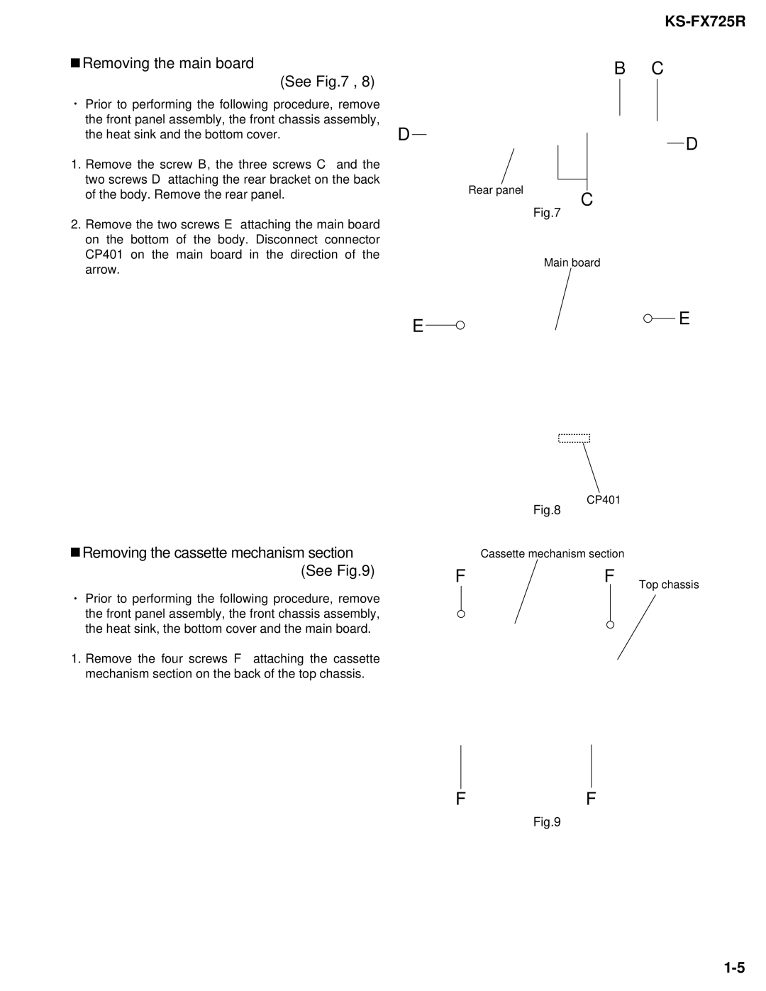
Removing the main board See
Removing the control switch board See ~
Removing the head board See
Removing the reinforce bracket See
Removing the cassette guide See
Removing the load arm See
Removing the side bracket assembly See to
Removing the slide chassis assembly See
Removing the pinch arm F assembly See
Removing the pinch arm R assembly
Removing the head / tape guide See
Removing the flywheel assembly F & R See
Removing the reel board
Disassembling the flywheel assembly F See
Disassembling the flywheel assembly R See
Removing the FFC pad See
Removing the gear base arm / gear base link assembly See to
Removing the mode switch actuator See , 31
Removing the mode gear See
Removing the mode rack assembly See
Removing the direction link / direction plate See to
Removing the reel driver / reel spindle See
Eject cam plate spring Joint g Load rack
Removing the main motor assembly / sub motor assembly See to
Test instruments reqired for adjustment
Adjustment method
Standard volume position
Measuring conditionsAmplifier section
Arrangement of adjusting & test points
Disassembly method
Arrangment of adjusting
Information for using a car audio service jig
Conditions
UPD178018AGC584IC701 System controller micon
Description of major ICs
HA13158A IC941 Power amp
CXA2559QIC401Playback equalizer amplifier with music sensor
Pin layout 1021 Blockdiagram
Pin function
HA13164IC961REGULATOR
Block diagram
Rdcl
SAA6579T-XIC761RDS Detector
Pin layout Block diagram
TEA6320T-X IC911 E.volume
LC75823E IC651 LCD Driver
Pin Layout & Symbol
LB1641 IC402 DC motor driver
HD74HC126FP-X IC751 Buffer
Motor Head
Block diagram
M O
Receiver & System control section
Standard schematic diagrams
KS-FX725RKS-FX725R
Mecha control circuit section
LCD1
LCD driver & Operation switch section
Main board
Printed circuit boards
Front boardForward side
Front boardReverse side
Parts List
List
Parts number Parts name Qty Description Area
Parts list General assembly
Block No. M1MM
Spacer
Cassette mechanism assembly and parts list
Block No. Mpmm
Parts list Cassette mechanism
Gear Base SPG
Grease point 1/2
Grease point 2/2
Electrical parts list Main board
UDZS5.6B-X Zener Diode
MG Resistor
Electrical parts list Mecha control board
Electrical parts list Front board
M O
Packing materials and accessories parts list
Parts list Accessories
Parts list Packing
Block No. M3MM
Block No. M5MM
KS-F525
KS-FX725R/KS-F525
Òîëüêî â îòíîøåíèè KS-FX725R
Содержание
Кàê ïåðåíàñòðîèòü Вàøå óñòðîéñòâî
Оêíî íà ýêðàíå äèñïëåя
Расположение Кнопок
Пàíåëü óïðàâëåíèя-KS-FX725R
Пàíåëü óïðàâëåíèя-KS-F525
Вêëþ÷åíèå
Основные Операции
Чòîáû ìîìåíòàëüíî ïîíèçèòü ãðîìêîñòü
Чòîáû âûêëþ÷èòü óñòðîéñòâî
Аâòîìàòè÷åñêèé ïîèñê
Пðîñëóøèâàíèå ðàäèî
Ðàäèîñòàíöèè Аâòîìàòè÷åñêèé
Ïîèñê
FM1 FM2 FM3 AM
Пîèñê ðàäèîñòàíöèè âðó÷íóþ Рó÷íîé ïîèñê
Рó÷íîå ïðîãðàììèðîâàíèå
Сîõðàíåíèå ðàäèîñòàíöèé â ïàìяòè
Аâòîìàòè÷åñêîå Ïðîãðàììèðîâàíèå ðàäèîñòàíöèé FM SSM
Нàñòðîéêà íà çàïðîãðàììèðîâàííóþ ðàäèîñòàíöèþ
Рåæèì
Операции С RDS
Чòî Вû ìîæåòå äåëàòü ñ ïîìîùüþ RDS
Рåçåðâíûé ïðèåì PTY
Иñïîëüçîâàíèå ðåçåðâíîãî ïðèåìà
Рåçåðâíûé ïðèåì ТА
Чòîáû çàïîìíèòü Вàøè ëþáèìûå òèïû ïðîãðàìì
Вûáîð Вàøåé ëþáèìîé ïðîãðàììû äëя ðåçåðâíîãî ïðèåìà PTY
Пîèñê Вàøåé ëþáèìîé ïðîãðàììû
Чòîáû íàéòè Вàø ëþáèìûé òèï ïðîãðàìì
Аâòîìàòè÷åñêèé âûáîð ñòàíöèè ñ ïîìîùüþ íóìåðîâàííûõ êíîïîê
Аâòîìàòè÷åñêàя ðåãóëèðîâêà ÷àñîâ
Уñòàíîâêà óðîâíя ãðîìêîñòè ТА
Affairs
Кîäû PTY
Уñêîðåííàя ïåðåìîòêà âïåðåä è ïåðåìîòêà íàçàä ëåíòû êàññåòû
Пðîñëóøèâàíèå êàññåòû
Вñòàâüòå êàññåòó â êàññåòîïðèåìíèê
Вûáîð íàïðàâëåíèя âîñïðîèçâåäåíèя êàññåòû
Пðåäîòâðàùåíèå âûñêàêèâàíèя êàññåòû
Нàõîæäåíèå íà÷àëà ìåëîäèè
Пðîïóñê ïóñòûõ ó÷àñòêîâ íà êàññåòå
Дðóãèå ïîëåçíûå ôóíêöèè ìàãíèòîôîíà
Пîâòîðíîå âîñïðîèçâåäåíèå òåêóùåé ìåëîäèè
Нàæìèòå íà êíîïêó SEL âûáîð, ÷òîáû çàêîí÷èòü óñòàíîâêó
Нàñòðîéêà çâóêà
Настройка Звука
Вûáåðèòå òîò ïàðàìåòð, êîòîðûé Вû õîòèòå íàñòðîèòü
Нàñòðîéòå óðîâåíü
Ôóíêöèè êîìïåíñàöèè Ãðîìêîñòè
Вêëþ÷åíèå/âûêëþ÷åíèå
Иñïîëüçîâàíèå ïàìяòè óïðàâëåíèя çâóêîì
Вûáîð è çàïîìèíàíèå ðåæèìîâ çâó÷àíèя
Иíäèêàöèя Дëя Зàïðîãðàììèðîâàííûå Çíà÷åíèя
Пîâòîðíûé âûçîâ ðåæèìîâ çâó÷àíèя
Вàøèõ ñîáñòâåííûõ
Сîõðàíåíèå â ïàìяòè
Íàñòðîåê çâóêà
Ha KS-FX725R
Оñíîâíàя ïðîöåäóðà
Другие Главные Функции
Уñòàíîâêà ÷àñîâ
24H/12H
Пàðàìåòðû ïðåäïî÷òèòåëüíîãî ðåæèìà óñòàíîâêè PSM
3, ÷òîáû íàñòðîèòü äðóãèå
Чòîáû âûáðàòü âíåøíèé êîìïîíåíò äëя èñïîëüçîâàíèя
Дëя âûáîðà ïðèãëóøåíèя çâóêà ïðè òåëåôîííîì çâîíêå
Дëя âûáîðà óðîâíåìåðà
Кàê ïðèñîåäèíèòü ïàíåëü óïðàâëåíèя
Оòñîåäèíåíèå ïàíåëè óïðàâëåíèя
Кàê îòñîåäèíèòü ïàíåëü óïðàâëåíèя
Вûáåðèòå ïðîèãðûâàòåëü-àâòîìàò êîìïàêò-äèñêîâ CD-CH
Операции С ПРОИГРЫВАТЕЛЕМ- Автоматом КОМПАКТ-ДИСКОВ
Вîñïðîèçâåäåíèå êîìïàêò-äèñêîâ
Дëя óñêîðåííîé ïåðåìîòêè âïåðåä èëè ïåðåìîòêè íàçàä ê òðåêó
Вûáîð ðåæèìîâ âîñïðîèçâåäåíèя êîìïàêò-äèñêîâ
Чòîáû ïåðåéòè ïðяìî íà êîíêðåòíûé äèñê
Оòìåíåíî
Вîñïðîèçâåäåíèå íà âíåøíåì êîìïîíåíòå
Операции С Внешними Компонентами
Нàñòðîéêà íà ãðóïïó è îäíó èç ñëóæá
Операции С Тюнером DAB
Чòî ïðåäñòàâëяåò ñîáîé ñèñòåìà DAB?
Вûáåðèòå òþíåð DAB
Чòîáû âîññòàíîâèòü òþíåð FM/AM
Чòîáû íàñòðîèòüñя íà îïðåäåëåííóþ ãðóïïó áåç ïîèñêà
Нà÷èíàéòå ïîèñê ãðóïïû
Вûáåðèòå ñëóæáó, êîòîðóþ Вû õîòèòå ñëóøàòü
Сîõðàíåíèå ñëóæá DAB â ïàìяòè
Нàñòðîéêà íà çàïðîãðàììèðîâàííóþ ñëóæáó DAB
Сèìïòîìû Пðè÷èíû Сïîñîá óñòðàíåíèя
Выявление Неисправностей
Òîëüêî â îòíîøåíèè KS-FX725R
Пîääåðæàíèå ÷èñòîòû êàññåò
Техническое Обслуживание
Чèñòêà ãîëîâêè
Секция Усилителя Звуковой Частоты
Технические Характеристики
Having Trouble with operation? Please reset your unit
Установка Установка В Приборную Панель
KS-FX725R/KS-F525
Electrical Connections Электрические Подключения
Parts list for installation and connection
Removing the unit
Уäàëåíèå óñòðîéñòâà
Typical Connections / Тèïè÷íûå ïîäêëþ÷åíèя
Precautions on power supply and speaker connections
Предостережения ïî ïèòàíèþ è ïîäêëþ÷åíèþ ãðîìêîãîâîðèòåëåé
Only for KS-FX725R
Troubleshooting Bыявление Неисправностей
KS-FX725R/KS-F525
Contents
Display window
Location of the Buttons
Control panel-KS-FX725R
Control panel-KS-F525
To drop the volume in a moment
Turning on the power
To turn off the power
Basic Operations
Listening to the radio
Radio Basic Operations
Searching a station automatically Auto search
Start searching a station
Searching a station manually Manual search
When an FM stereo broadcast is hard to receive
To restore the stereo effect, press the same
Select the FM band FM1 3 you want to store FM stations into
FM station automatic preset SSM
Manual preset
Scanning broadcast stations
Select the number 1 6 for the preset
Tune in to a station in this example, of 88.3 MHz
Only for KS-F525
What you can do with RDS
RDS Operations
This section is only for KS-FX725R
Mode
PTY Standby Reception
Using Standby Reception
TA Standby Reception
To deactivate the TA standby mode, press TP
Searching your favorite programme
Press SEL select to finish the setting
Selecting your favorite programme for PTY Standby Reception
To store your favorite programme types
Other convenient RDS functions and adjustments
Listening to an FM station
Changing the display mode while
Automatic clock adjustment
Folk M
PTY codes
Listening to a cassette
Tape Operations
To stop play and eject the cassette
To fast-forward and rewind a tape
Finding the beginning of a tune
To cancel the prohibition and unlock
Prohibiting cassette ejection
During playback
Playing the current tune repeatedly
Other convenient tape functions
Adjusting the sound
Sound Adjustments
Select the item you want to adjust
Adjust the level
Function
Select the sound mode you want
Selecting and storing the sound modes
Advanced SCM
Recalling the sound modes
When SCM Link is set to Link ON, select the source
Indication For Preset values
To reset to the factory settings
Storing your own sound adjustments
Changing the general settings PSM
Setting the clock
Basic Procedure
Other Main Functions
24H/ 12H
Preferred Setting Mode PSM items
To select the telephone muting TEL
To cancel Advanced SCM SCM Link
To select the level meter Level
To select the external component to use
Unlock the control panel
Detaching the control panel
Attaching the control panel
Playing CDs
CD Changer Operations
To fast-forward or reverse the track
Select the CD automatic changer CD-CH
To go to a particular disc directly
Canceled
To play back tracks at random Random Play
To play back tracks repeatedly Repeat Play
External Component Operations
DAB Tuner Operations
What is DAB system?
Select the DAB tuner
Select the DAB band DAB1, DAB2, or DAB3
To restore the FM/AM tuner
Tuning in to an ensemble
Select a service you want to listen to
Start searching an ensemble
Select the DAB band DAB1, DAB2 or DAB3 you want
Storing DAB services
Memory
Tuning in to a preset DAB service
Symptoms Causes Remedies
Troubleshooting
Only for KS-FX725R
To clean the head
Maintenance
To keep the tape clean
Ignition key-off release/Ignition key-on play
MW Tuner
Specifications
LW Tuner
FM Tuner
Having Trouble with operation? Please reset your unit
KS-FX725R/KS-F525
Electrical Connections Электрические Подключения
Typical Connections / Тèïè÷íûå ïîäêëþ÷åíèя
Troubleshooting Bыявление Неисправностей
KS-FX725R

 Removing the cassette mechanism section (See Fig.9)