XV-C5SL
Changing the initial set
Important for Laser Products
Supplied accessories
Precautions
Table of contents
About this manual
Before operation
About discs
Playable disc types
Unplayable discs
Cleaning discs
Care and handling of discs
Handling
Storing discs
Preparations
Connecting to a TV
Connections
Connecting to optional audio equipment
Connecting to a stereo audio amplifier/ receiver
Connecting to a digital audio device
Right LEFTAmplifier or receiver Red White
Installation
Connecting the power cord
How to attach the cover
Horizontal installation
Face-up installation
Vertical installation
Installation on the wall
Using the remote control unit
To install batteries
Precautions of the safe use of batteries
Remote sensor
To use the remote control unit for TV operation
To control the volume of a JVC’s amplifier or receiver
To set the remote control signal for operating your TV
Press Enter
Initial setup
Basic operations
Turning on/off the unit
About invalid operation icon
To bring up the DVD Player SET UP display later
Press 5/∞ to select a desired digital output signal type
To change the brightness of the display window
Press 5/∞ to select the desired language
Basic playback
About PBC Playback Control
If a menu is shown on the TV screen
To check the playback status
Resuming playback
During playback, press ¡ on the remote control unit
During playback, press ¡ or 1 on the remote control unit
Various speed playback
X1.5 Quick Playback with sound To resume playback
Using the numeric buttons
Locating the beginning of a scene or song
To advance a still picture frame by frame
To play back in slow motion
Locating a desired scene from the DVD menu
Advanced operations
Specifying a desired title
To dismiss the menu bar
Press on Screen twice
Press 2/3 to move to
Press the numeric buttons 0 to 9 to enter the desired time
To play back in a specific order
Changing the playback order
Program play
To play back in random order Random play
Repeat playback
To repeat the current selection or all tracks
Changing the language, sound and scene angle
To select the subtitle language Subtitle
To repeat a desired part A-B repeat playback
To quit A-B repeat playback
During playback, press Audio
Press 5/∞ or Audio to select the desired audio
During playback, press Angle
Press 5/∞ or Angle to select the desired angle
To adjust the picture character VFP
Special picture/sound effect
To zoom in pictures
To release the zooming
To simulate surround sound 3D Phonic
To dismiss the 3D Phonic window
Basic operation procedure
Menu bar functions
To bring up the menu bar
Menu bar functions for DVD Video
Menu bar functions for SVCD/Video CD/Audio CD
Subtitle selection See also
PROG. Program playback See also
While stopped, specifies the playback order of tracks
MP3 disc playback
Operations
About MP3 discs
Basic operations
Direct selection
Press 5/∞ to move the bar to a desired group
During playback or while stopped, press TITLE/GROUP
Press the numeric buttons to specify a desired group number
Repeat playback
During playback or while stopped, press Repeat
MP3 Control
Display Function Window
About Jpeg discs
Jpeg disc playback
Basic operations
Viewing pictures continuously slide show mode
To see a desired picture
To start the slide show
To select the start point of the slide show
To zoom in the picture
Repeat function
Direct selection
Changing the initial settings
How to set preferences
Selecting preferences
About the Preference display
Language menu
Picture menu
To dismiss a preference display
Press 5/∞ to select from the options then press Enter
Audio menu
You can set the screen saver function to on or OFF. See
ON, OFF
MP3, Jpeg
Wide RANGE, NORMAL, TV Mode
On when selected, the on-screen guide is activated
Others menu
STANDARD, LOW
Limiting playback by children
To set Parental Lock for the first time
Bring up the Others menu
Press 5/∞ to move To select Parental Lock then press Enter
To change the settings
You can change the parental lock settings later
To temporarily release the Parental Lock
Press 5/∞ to move To select Parental Lock and press Enter
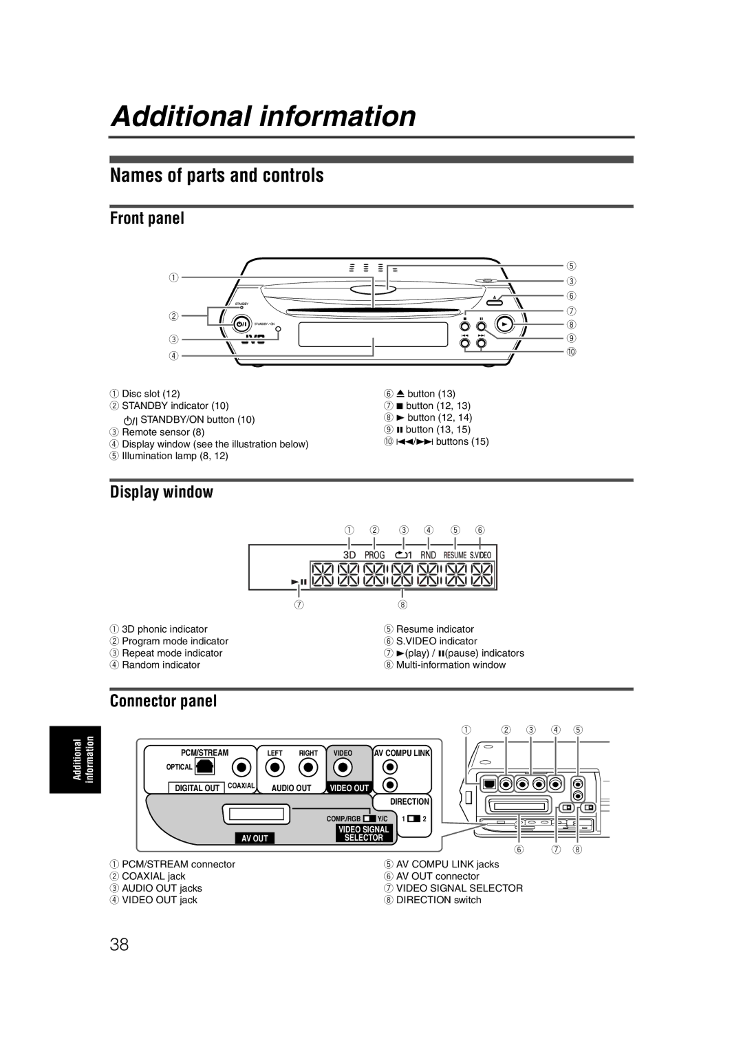
Connector panel
Additional information
Names of parts and controls
Front panel
Remote control unit
+10
Troubleshooting
Power
Audio
Operation
Specifications
Appendix a Country/Area code list for Parental Lock
For
Appendix C Digital output signal chart
Output Disc type
Appendix D Glossary
0303YIYMDWJSC
Victor Company of JAPAN, Limited