AV COMPU LINK Remote Control System
The AV COMPU LINK remote control system allows you to operate JVC’s video components (TV, VCR, and DVD player) through the receiver.
This receiver is equipped with the AV COMPU
To use this remote control system, connect the video components you want to operate, following the diagrams below and the procedure on the next page.
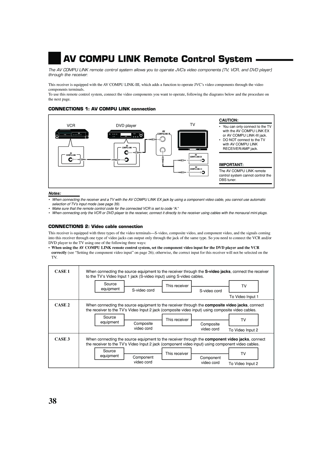
CONNECTIONS 1: AV COMPU LINK connection
VCR
VHS |
AV
COMPU LINK
DVD player
DVD |
AV
COMPU LINK
AV
COMPULINK- ![]()
TV
AV
COMPU LINK EX
AV
COMPU
CAUTION:
•You can only connect to the TV with the AV COMPU LINK EX or AV COMPU
•DO NOT connect to the TV with AV COMPU LINK RECEIVER/AMP jack.
IMPORTANT:
The AV COMPU LINK remote control system cannot control the DBS tuner.
Notes:
•When connecting the receiver and a TV with the AV COMPU LINK EX jack by using a component video cable, you cannot use automatic selection of TV’s input mode (see page 39).
•Make sure that the remote control code for the connected VCR is set to code “A.”
•When connecting only the VCR or DVD player to the receiver, connect it directly to the receiver using cables with the monaural
CONNECTIONS 2: Video cable connection
This receiver is equipped with three types of the video
•When using the AV COMPU LINK remote control system, set the component video input for the DVD player and the VCR correctly (see “Setting the component video input” on page 26); otherwise, the correct input for this receiver will not be selected on the TV.
CASE 1 | When connecting the source equipment to the receiver through the | ||||||
| to the TV’s Video Input 1 jack |
|
| ||||
|
|
|
|
|
|
|
|
|
| Source |
| This receiver |
| TV |
|
|
| equipment |
| ||||
|
|
|
|
| |||
|
|
|
|
|
| ||
|
|
|
|
|
| To Video Input 1 | |
|
|
|
|
|
|
|
|
CASE 2 | When connecting the source equipment to the receiver through the composite video jacks, connect | ||||||
| the receiver to the TV’s Video Input 2 jack (composite video input) using composite video cables. | ||||||
|
|
|
|
|
|
|
|
|
| Source |
| This receiver |
| TV |
|
|
| equipment | Composite | Composite |
| ||
|
|
|
|
| |||
|
|
|
|
|
| ||
|
|
| video cord |
| video cord | To Video Input 2 | |
|
|
|
|
|
|
|
|
CASE 3 | When connecting the source equipment to the receiver through the component video jacks, connect | ||||||
| the receiver to the TV’s Video Input 2 jack (component video input) using component video cables. | ||||||
|
|
|
|
|
|
|
|
|
| Source |
| This receiver |
| TV |
|
|
| equipment | Component | Component |
| ||
|
|
|
|
| |||
|
|
|
|
|
| ||
|
|
| video cord |
| video cord | To Video Input 2 | |
|
|
|
|
|
|
|
|
38