Preliminary knowledge
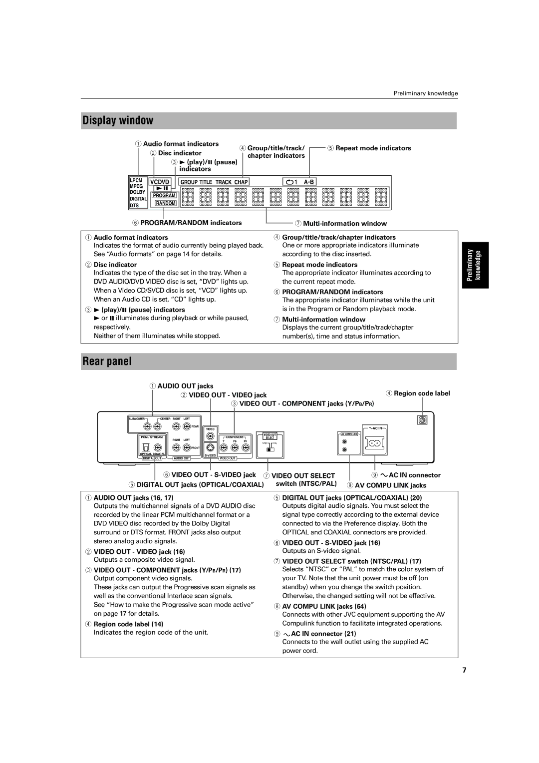
Display window
|
|
| 1 Audio format indicators | 4 Group/title/track/ |
|
| 5 Repeat mode indicators | ||||||||||||||
|
|
|
| 2 Disc indicator |
|
| |||||||||||||||
|
|
|
|
|
| chapter indicators |
|
|
|
|
| ||||||||||
|
|
|
|
|
| 3 3 (play)/8 (pause) |
|
|
|
|
|
|
| ||||||||
|
|
|
|
|
|
|
|
|
|
|
|
|
|
|
|
|
| ||||
|
|
|
|
|
|
|
|
| indicators |
|
|
|
|
|
|
|
|
|
|
|
|
|
|
|
|
|
|
|
|
|
|
|
|
|
|
|
|
|
|
|
|
| |
|
|
|
|
|
|
|
|
|
|
|
|
|
|
|
|
|
|
|
| ||
|
|
| LPCM |
|
|
|
|
|
|
|
|
|
|
|
|
|
|
|
|
| |
|
|
| VCDVD |
|
|
| GROUP TITLE TRACK CHAP |
|
|
|
| 1 A- | B |
|
|
|
| ||||
|
|
| MPEG | 38 |
|
|
|
|
|
|
|
|
|
|
|
|
|
|
|
| |
|
|
| DOLBY |
|
|
|
|
|
|
|
|
|
|
|
|
|
|
|
| ||
|
|
| PROGRAM |
|
|
|
|
|
|
|
|
|
|
|
|
|
| ||||
|
|
| DIGITAL |
|
|
|
|
|
|
|
|
|
|
|
|
|
| ||||
|
|
|
|
|
|
|
|
|
|
|
|
|
|
|
|
|
|
|
|
| |
|
|
| DTS | RANDOM |
|
|
|
|
|
|
|
|
|
|
|
|
|
| |||
|
|
|
|
|
|
|
|
|
|
|
|
|
|
|
|
|
|
|
|
| |
|
|
|
|
|
|
|
|
|
|
|
|
|
|
|
|
|
| ||||
|
|
| 6 PROGRAM/RANDOM indicators |
|
|
|
| 7 | |||||||||||||
|
|
|
|
|
|
| |||||||||||||||
|
|
|
|
|
|
|
|
|
|
|
|
|
|
|
|
|
|
|
| ||
1 Audio format indicators |
|
|
|
| 4 Group/title/track/chapter indicators | ||||||||||||||||
| Indicates the format of audio currently being played back. | One or more appropriate indicators illuminate | |||||||||||||||||||
| See “Audio formats” on page 14 for details. |
|
|
|
| according to the disc inserted. | |||||||||||||||
2 Disc indicator |
|
|
|
|
|
|
|
|
|
| 5 Repeat mode indicators | ||||||||||
| Indicates the type of the disc set in the tray. When a |
|
| The appropriate indicator illuminates according to | |||||||||||||||||
| DVD AUDIO/DVD VIDEO disc is set, “DVD” lights up. | the current repeat mode. | |||||||||||||||||||
| When a Video CD/SVCD disc is set, “VCD” lights up. |
|
| 6 PROGRAM/RANDOM indicators | |||||||||||||||||
| When an Audio CD is set, “CD” lights up. |
|
|
|
| The appropriate indicator illuminates while the unit | |||||||||||||||
3 | 3 | 8 |
|
|
|
|
|
|
|
|
|
|
| is in the Program or Random playback mode. | |||||||
| (play)/ (pause) indicators |
|
|
|
|
|
|
|
|
|
|
|
| ||||||||
| 3 or 8 illuminates during playback or while paused, | 7 | |||||||||||||||||||
| respectively. |
|
|
|
|
|
|
|
|
|
| Displays the current group/title/track/chapter | |||||||||
| Neither of them illuminates while stopped. |
|
|
|
| number(s), time and status information. | |||||||||||||||
|
|
|
|
|
|
|
|
|
|
|
|
|
|
|
|
|
|
|
|
|
|
Rear panel
Preliminary | knowledge |
|
|
1AUDIO OUT jacks
2 VIDEO OUT - VIDEO jack | 4 Region code label |
3VIDEO OUT - COMPONENT jacks (Y/PB/PR)
SUBWOOFER | CENTER | RIGHT | LEFT |
|
|
|
|
|
|
|
| REAR |
|
|
|
| AC IN |
|
|
| VIDEO |
|
|
|
| |
PCM / STREAM |
|
|
| COMPONENT | VIDEO OUT | AV COMPU LINK | ||
RIGHT | LEFT |
| SELECT |
| ||||
|
| Y | PB | PR |
|
| ||
|
|
|
|
|
| NTSC | PAL |
|
|
|
| FRONT |
|
|
|
|
|
OPTICAL COAXIAL |
|
|
|
|
|
| ||
DIGITAL OUT |
| VIDEO OUT |
|
|
| |||
AUDIO OUT |
|
|
| |||||
6 VIDEO OUT - | 9 AC IN connector |
5 DIGITAL OUT jacks (OPTICAL/COAXIAL) switch (NTSC/PAL) | 8 AV COMPU LINK jacks |
1AUDIO OUT jacks (16, 17)
Outputs the multichannel signals of a DVD AUDIO disc recorded by the linear PCM multichannel format or a DVD VIDEO disc recorded by the Dolby Digital surround or DTS format. FRONT jacks also output stereo analog audio signals.
2VIDEO OUT - VIDEO jack (16) Outputs a composite video signal.
3VIDEO OUT - COMPONENT jacks (Y/PB/PR) (17) Output component video signals.
These jacks can output the Progressive scan signals as well as the conventional Interlace scan signals.
See “How to make the Progressive scan mode active” on page 17 for details.
4Region code label (14)
Indicates the region code of the unit.
5DIGITAL OUT jacks (OPTICAL/COAXIAL) (20) Outputs digital audio signals. You must select the signal type correctly according to the external device connected to via the Preference display. Both the OPTICAL and COAXIAL connectors are provided.
6VIDEO OUT -
7VIDEO OUT SELECT switch (NTSC/PAL) (17) Selects “NTSC” or “PAL” to match the color system of your TV. Note that the unit power must be off (on standby) when you change the switch position. Otherwise, the changed setting will not be effective.
8AV COMPU LINK jacks (64)
Connects with other JVC equipment supporting the AV Compulink function to facilitate integrated operations.
9![]() AC IN connector (21)
AC IN connector (21)
Connects to the wall outlet using the supplied AC power cord.
7