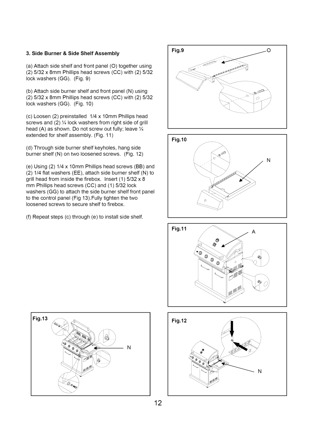
3. Side Burner & Side Shelf Assembly
(a) Attach side shelf and front panel (O) together using |
(2) 5/32 x 8mm Phillips head screws (CC) with (2) 5/32 |
lock washers (GG). (Fig. 9) |
(b) Attach side burner shelf and front panel (N) using |
(2) 5/32 x 8mm Phillips head screws (CC) with (2) 5/32 |
lock washers (GG). (Fig. 10) |
(c) Loosen (2) preinstalled 1/4 x 10mm Phillips head |
screws and (2) ¼ lock washers from right side of grill |
head (A) as shown. Do not screw out fully; leave ¼ |
extended for shelf assembly. (Fig. 11) |
Fig.9iO
(d) Through side burner shelf keyholes, hang side |
burner shelf (N) on two loosened screws. (Fig. 12) |
(e) Using (2) 1/4 x 10mm Phillips head screws (BB) and |
(2) 1/4 flat washers (EE), attach side burner shelf (N) to |
grill head from inside the firebox. Insert (1) 5/32 x 8 |
mm Phillips head screws (CC) and (1) 5/32 lock |
washers (GG) to attach the side burner shelf front panel |
to the control panel (Fig 13).Fully tighten the two loosened screws to secure shelf to firebox.
(f) Repeat steps (c) through (e) to install side shelf.
Fig.13
N
Fig.10
Fig.11
Fig.12
N
A
\\\\\,
N
12