Installation Instructions
Temperature-Pressure
Relief Valve
_,WARNING
At the time of manufacture this water heater was provid- ed with a combination
equipment or materials, as meeting the requirements for
Relief Valves and Automatic Gas Shutoff Devices for Hot
Water Supply Systems, and the latest edition of ANSI Z21.22 and the code requirements of ASHE. If replaced, the valve must meet the requirements of local codes,but
not less than a combination temperature and pressure relief valve certified as meeting the requirements for
Relief Valves and Automatic Gas Shutoff Devices for Hot Water SupplySystems,ANSI Z21.22 bya nationallyrecog- nized testing laboratory that maintains periodic inspection of production of listed equipment or materials.
The valve must be marked with a maximum set pressure not to exceed the marked hydrostaticworking pressureof the water heater (150 Ibs./sq.in.) and a dischargecapacity not lessthan the water heater input rate as shownon the model rating plate. (Electric heaters - watts divided by 1000 x 3415 equal BTU/Hr. rate.)
Your localjurisdictionalauthority, while mandatingthe use of a
ANSI Z21.22 and ASME, may require a valve model differ- ent from the one furnishedwith the water heater.
Compliance with such local requirements must be satis- fied by the installer or end user of the water heater with a locally prescribed
For safe operation of the water heater, the relief valve must not be removed from it'sdesignated opening or plugged.
The
reduced in size under any circumstances.Excessivelength, over 30 feet, or use of more than four elbows can cause restriction and reduce the dischargecapacityof the valve.
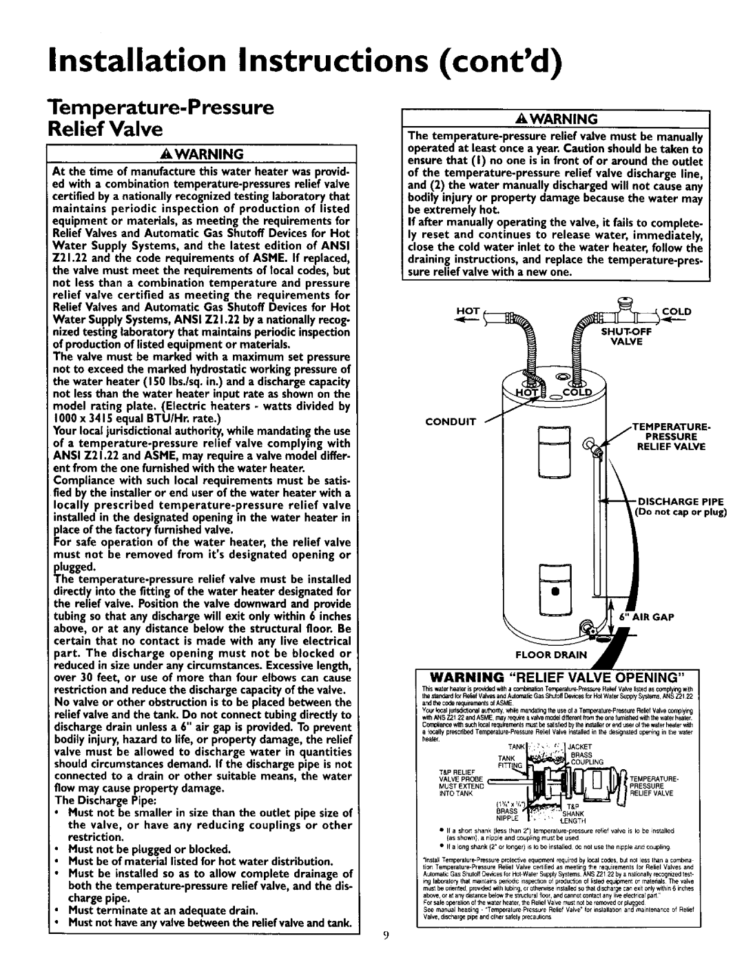
No valve or other obstruction is to be placedbetween the relief valve and the tank. Do not connecttubingdirectly to dischargedrain unlessa 6" air gap is provided.To prevent bodily injury, hazard to life, or property damage, the relief valve must be allowed to discharge water in quantities shouldcircumstancesdemand. If the dischargepipe is not connected to a drain or other suitable means, the water flow may causeproperty damage.
The DischargePipe:
•Must not be smaller in size than the outlet pipe size of
the valve, or have any reducing couplings or other restriction.
Must not be pluggedor blocked.
Must be of material listedfor hot water distribution.
Must be installed so as to allow complete drainage of both the
Must terminate at an adequate drain.
Must not haveanyvalvebetweenthe relief valveand tank.
(cont'd)
•, WARNING
The
be extremely hot.
If after manually operating the valve, it fails to complete- ly reset and continues to release water, immediately, close the cold water inlet to the water heater, follow the
draining instructions, and replace the
H_OT ( | COLD |
VALVE
CONDUIT J
TEMPERATURE-
J PRESSURE
RELIEF VALVE
DISCHARGE PIPE
Do not cap or plug)
6" AIR GAP
r
FLOOR DRAIN •
WARNING "RELIEF VALVE OPENING"
Thiswaterheateris p_ovidedwilha co,_on Tempe_ Press_e Re_efValvelistedasco_plyingw_h the standardfo_RediQfValws andAulomalicGasShutoffDewcesforH01WaterSupp_Systems,ANSZ2122 andthecoderequirementsofASME
Yc_'lc_ judsd_tl,0nalau_hontywhle rn_ndatingtheuseof a
withANS721 22andASME,may_Ie a vah.emodeldlffelentPoretheonefurnished_ thewaterheater Comp_ar_ewithsuchlocalrequirements_st be_ltisfbedby theinslallerc_ endt_el of thewaterheater_h
alegally
TANK : '_ ; t, JACKET
TANK * , 1" r_., BRASS
FITTINGCOUPLING
VALVE PROBE | TEMPERATURE- |
MUST EX_rEND | PRESSURE |
iNTO TANK | RELIEFVALVE |
BRASS | SHANK |
•I1 a short shank (less lhan 2")
•If a long shank (2" of loiter) is IO be in sla_led d<Jriot us_ the nipple end coupling
"Ins{all Tempetalure.Pre_ure | prolective equipmenl | _uir_ | by | local codes but nol less If,an | a combine | |
lion | Relic I Valve cetli{ied | as meeting | the requirernenls | lot Reliel | Valves and | |
Aulomauc Gas Shuloff
rig labO_alory that r_ant ains peno_c ft_spection of production o{ lisle_ equipment el rnatehals The valve mUSl he onenled provKled _th lubin9, or olhen_se i_slaJlod SOthat discUarge can exit only _thin 6 inches above¸ o, at any d_stance below Ibe 5tnJcforel flOOr, and cannot contact any live electlica_ part
For safe operalio_ of the water heatel, the Rehef Valve must not be iemoved or plugged¸
See maflua_ headirlg. "Temperah_re Pressure Relief Valve" {of il_slallatitl_ and mainlenance of Relief Valve, discharg_ p_pe and elher salety pr_autions