Installation Instructions
Temperature-Pressure
Relief Valve
_,WARNING
At the time of manufacture this water heater was provided with a combination
ment or materials, as meeting the requirements for Relief
Valves and Automatic Gas Shutoff Devices for Hot Water Supply Systems, and the current edition of ANSI Z21.22 , CSA 4.4 and the code requirements of ASHE. If replaced, the valve must meet the requirements of local codes, but
not less than a combination temperature and pressure
relief valve certified as meeting the requirements for Relief
Valves and Automatic Gas Shutoff Devices for Hot Water Supply Systems, ANSI Z21.22, CSA 4.4 by a nationally rec- ognized testing laboratory that maintains periodic inspec- tion of production of listed equipment or materials.
The valve must be marked with a maximum set pressure not to exceed the marked hydrostatic working pressure of the water heater (150 Ibs. p.s.i.) and a discharge capacity not less than the water heater input rate as shown on the model rating plate. (Electric heaters - watts divided by 1000 x 3412 equal BTU/Hr. rate.)
Your local jurisdictional authority, while mandating the use of a
Z21.22, CSA 4.4 and ASME, may require a valve model dif- ferent from the one furnished with the water heater.
Compliance with such local requirements must be satisfied by the installer or end user oftbe water heater with a local- ly prescribed
For safe operation of the water heater, the relief valve must not be removed from it'sdesignated opening or plugged.
The
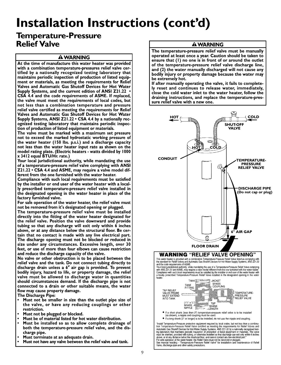
No valve or other obstruction is to be placed between the relief valve and the tank. Do not connect tubing directly to discharge drain unless a 6" air gap is provided. To prevent bodily injury, hazard to life, or property damage, the relief valve must be allowed to discharge water in quantities should circumstances demand. If the discharge pipe is not connected to a drain or other suitable means, the water flow may cause property damage.
The Discharge Pipe:
Must not be smaller in size than the outlet pipe size of
the valve, or have any reducing couplings or other restriction.
Must not be plugged or blocked.
Must be of material listed for hot water distribution.
Must be installed so as to allow complete drainage of both the
Must terminate at an adequate drain.
Must not haveany valve between the relief valve and tank.
(cont'd)
&WARNING
The
If after manually operating the valve, it fails to complete- ly reset and continues to release water, immediately, close the cold water inlet to the water heater, follow the
draining instructions, and replace the
COLD
H_OT(
VALVE
CONDUIT
RELIEF VALVE
__PRESSURE
(Do not cap or plug)
6" AIR GAP
WARNING "RELIEF VALVE OPENING"
and the codel_Ji_rnent_ OfASME
Compliance_th suchlocal iequilem_'_iitsst besa_sf_,dby th#instaHexol end _sel of th_ waterheatelw_h
a locally plescribe_JTempelature*Pl_ssureReliefValv_ installedin the designated _ning in the watel heater
•If a short shank (less than 2") temperaltJle.plessurereltef valve is to be installed (_Sshown), _ nipple and coupling must be tJsed
•If _ long sha_k/2" or Io_ger) is to be instalEed,do not use the nippEea_d coupling
Aulomat_cGas ShutoffDc_4cesfor Hot.WatclSupply Systems,ANS Z2122 by a nationallyrccognizeitcs_* inglaboratory_hatmant_ns pcdodlcinspec_o_Of production oi listedeq_prn_t or matexials The valve m_s_beodente_J,prov_ed _lh tubing, ol ot_er_se inst_ledso that dischal_ecmqex_only w_hi_6 inches
above, Orat a_y dis_ancb_ow the s_ructuralflocl,and cannotcontact any I_veclcctrlcalpar[¸" Fol safeopclat_onof _hcwa_elbeatel,_hcReliefVa_e m_s_r_t be icmovedorpl_gecd
See mant_alhcadin_- =Temperat_rc*PiessuleRelief Valve" fol installatJonand ma_n_enanc_oi Relief Va_c, d_SChargcipeand othersafe_yprecat_ons
9