This appliance is one of the most advanced water heaters available. It provides a continuous supply of hot water at a preset temperature. This appliance is direct vent where air is brought in from the outside and combustion gases are exhausted to the outside.
While electricity, water, and gas supplies are connected, this appliance produces hot water whenever a hot water tap is open.
Ignition is electronic. There is no pilot light consuming gas while the water heater is not being used. The gas burner lights automatically when the hot water tap is
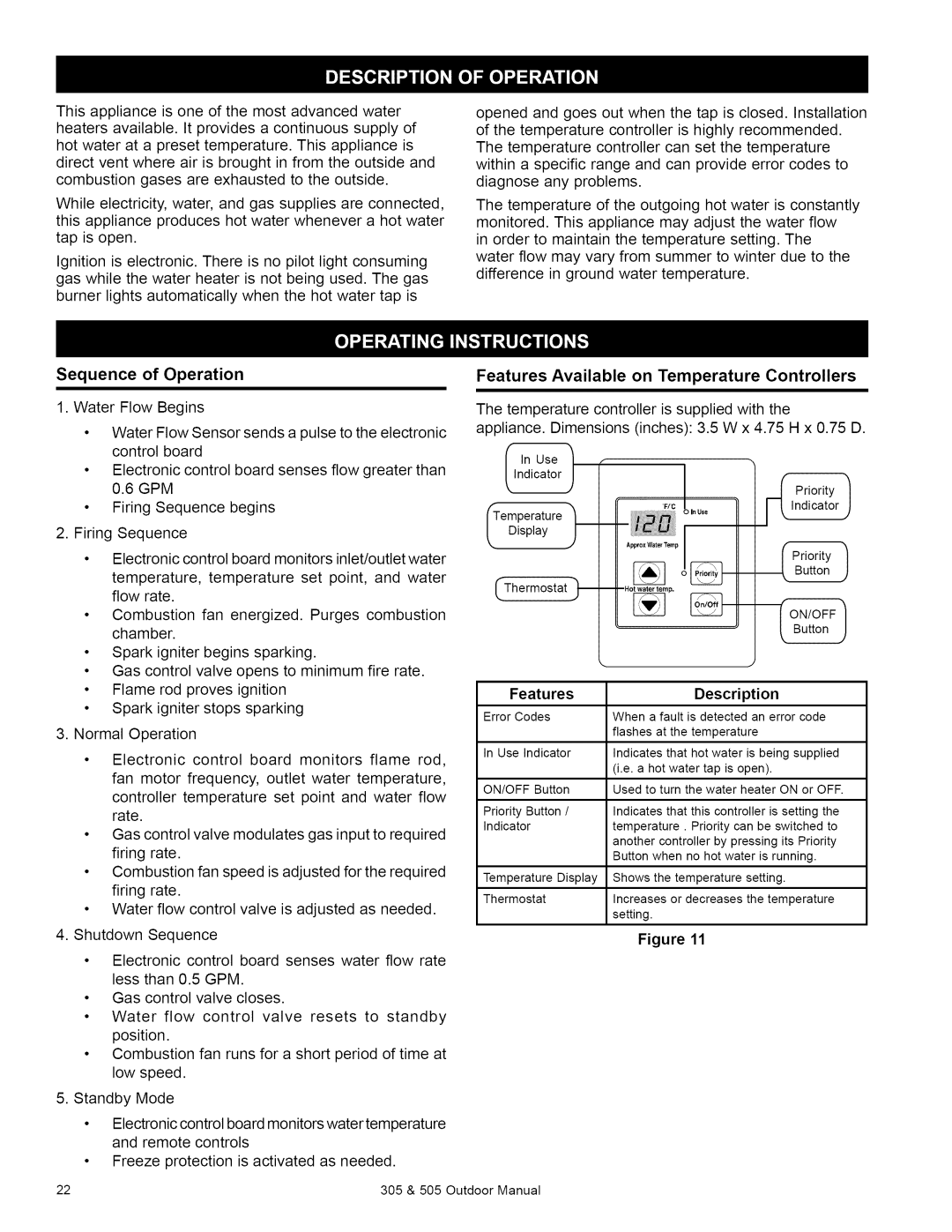
opened and goes out when the tap is closed. Installation of the temperature controller is highly recommended. The temperature controller can set the temperature within a specific range and can provide error codes to diagnose any problems.
The temperature of the outgoing hot water is constantly monitored. This appliance may adjust the water flow in order to maintain the temperature setting. The water flow may vary from summer to winter due to the difference in ground water temperature.
Sequence of Operation
1. Water | Flow Begins |
|
• | Water Flow Sensor sends a pulse to the electronic | |
| control board |
|
• | Electronic control | board senses flow greater than |
| 0.6 GPM |
|
• | Firing Sequence | begins |
Features Available on Temperature Controllers
The temperature controller is supplied with the
appliance. Dimensions (inches): 3.5 W x 4.75 H x 0.75 D.
Indicator
In Use 1
k, | J | Priority | / |
| I |
|
|
"F/'C
ITemperature
In Use
2. Firing Sequence |
|
|
|
| |||
• | Electronic control board monitors inlet/outlet water | ||||||
| temperature, temperature set point, and water | ||||||
| flow | rate. |
|
|
|
| |
• | Combustion fan energized. Purges combustion | ||||||
| chamber. |
|
|
|
| ||
• | Spark | igniter begins sparking. |
|
| |||
• | Gas control | valve | opens to minimum | fire rate. | |||
• | Flame | rod | proves | ignition |
|
| |
• | Spark | igniter stops sparking |
|
| |||
3. Normal Operation |
|
|
| ||||
• | Electronic | control board monitors flame rod, | |||||
| fan motor frequency, outlet water temperature, | ||||||
| controller temperature set point and water flow | ||||||
| rate. |
|
|
|
|
|
|
• | Gas control | valve | modulates gas input to required | ||||
| firing | rate. |
|
|
|
| |
• | Combustion | fan speed is adjusted for the required | |||||
| firing | rate. |
|
|
|
| |
• | Water | flow | control | valve is adjusted | as needed. | ||
4. Shutdown | Sequence |
|
|
| |||
• | Electronic | control board senses water flow rate | |||||
| less than 0.5 GPM. |
|
| ||||
• | Gas control | valve | closes. |
|
| ||
• | Water flow control valve resets | to | standby | ||||
| position. |
|
|
|
| ||
• | Combustion | fan runs for a short period | of time at | ||||
| low speed. |
|
|
|
| ||
5. Standby Mode |
|
|
|
| |||
• | Electronic control board monitors water temperature | ||||||
| and remote | controls |
|
| |||
• | Freeze | protection | is activated as needed. | ||||
Display F
Approx Water Temp
Features |
|
|
| Description |
|
| ||
Error Codes | When | a fault | is detected | an error | code | |||
|
| flashes | at | the temperature |
|
| ||
In Use Indicator | Indicates | that | hot water | is being | supplied | |||
|
| (i.e. a hot water tap is open). |
|
| ||||
ON/OFF | Button | Used to turn the water heater ON or OFF. | ||||||
Priority | Button / | Indicates | that | this controller is setting | the | |||
Indicator |
| temperature. | Priority can be switched | to | ||||
|
| another controller by pressing its Priority | ||||||
|
| Button when no hot water is running. |
| |||||
Temperature Display | Shows | the temperature | setting. |
|
| |||
Thermostat | Increases | or decreases | the temperature | |||||
|
| setting. |
|
|
|
|
|
|
Figure 11
22 | 305 & 505 Outdoor Manual |
