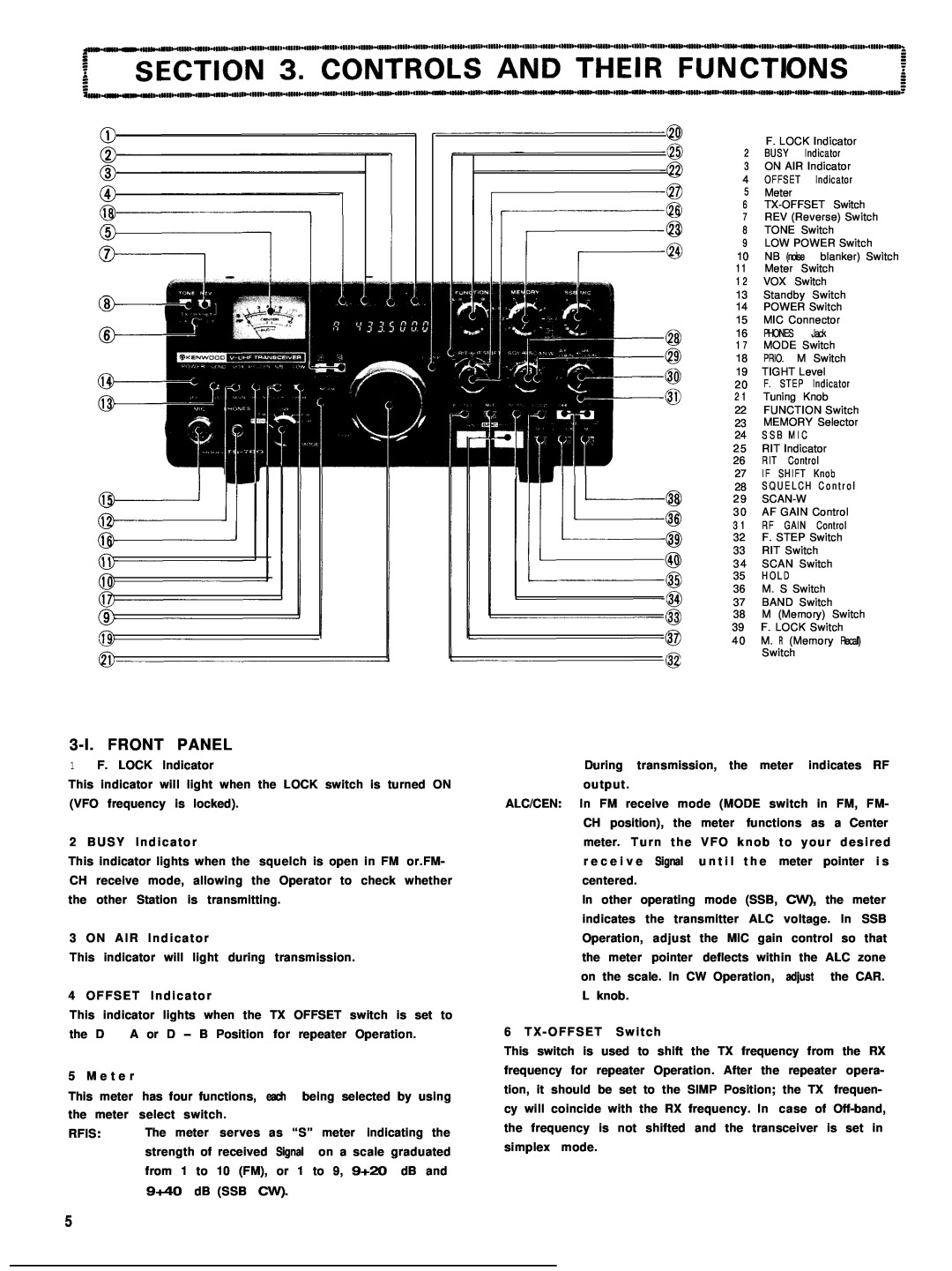
3-l. FRONT PANEL
1F. LOCK Indicator
This indicator will light when the LOCK switch is turned ON (VFO frequency is locked).
2 BUSY Indicator
This indicator lights when the squelch is open in FM or.FM-
CH | receive mode, allowing the Operator to check whether | ||||||||
the | other Station | is | transmitting. |
|
|
| |||
3 ON AIR | Indicator |
|
|
|
| ||||
This | indicator | will | light during | transmission. |
| ||||
4 OFFSET | Indicator |
|
|
|
| ||||
This | indicator | lights | when the | TX OFFSET switch is set to | |||||
the | D - A | or | D | - | B Position | for | repeater Operation. | ||
5 M e t e r |
|
|
|
|
|
|
|
| |
This | meter | has four functions, each | being selected | by using | |||||
the | meter select | switch. |
|
|
|
| |||
RFIS: | The meter serves | as | “S” | meter indicating the | |||||
|
| strength of received | Signal | on a scale graduated | |||||
|
| from 1 to 10 (FM), | or | 1 | to 9, 9+20 | dB and | |||
|
| 9+40 | dB (SSB CW). |
|
|
| |||
| F. LOCK Indicator | |||
2 | BUSY | Indicator | ||
3 | ON AIR Indicator | |||
4 | OFFSET | Indicator | ||
5 | Meter |
|
| |
6 | ||||
7 | REV (Reverse) Switch | |||
8 | TONE Switch | |||
9 | LOW POWER Switch | |||
10 | NB | (noise | blanker) Switch | |
1 1 | Meter | Switch | ||
1 2 | VOX Switch | |||
13 | Standby | Switch | ||
14 | POWER Switch | |||
15 | MIC Connector | |||
16 | PHONES |
| Jack | |
1 7 | MODE Switch | |||
18 | PRIO. |
| M | Switch |
19 | TIGHT Level | |||
2 0 | F. STEP | Indicator | ||
2 1 | Tuning | Knob | ||
22 | FUNCTION Switch | |||
23 | MEMORY Selector | |||
24 | S S B | M I C |
| |
2 5 | RIT Indicator | |||
26 | RIT | Control | ||
27 | IF SHIFT | Knob | ||
28 | S Q U E L C H C o n t r o l | |||
2 9 |
| |||
3 0 | AF GAIN Control | |||
3 1 | RF | GAIN | Control | |
32 | F. STEP Switch | |||
33 | RIT Switch | |||
3 4 | SCAN Switch | |||
35 | H O L D |
|
| |
36 | M. S Switch | |||
37 | BAND Switch | |||
38 | M (Memory) Switch | |||
39 | F. LOCK Switch | |||
4 0 | M. R | (Memory Recall) | ||
Switch
During transmission, the meter indicates RF output.
ALC/CEN: In FM receive mode (MODE switch in FM, FM-
CH position), | the | meter | functions as | a Center | |
meter. Turn | the | VFO | knob | to your | desired |
r e c e i v e Signal | u n t i l | t h e | meter pointer i s | ||
centered. |
|
|
|
|
|
In other operating mode (SSB, CW), the meter indicates the transmitter ALC voltage. In SSB
Operation, adjust the MIC gain | control so that | ||
the meter pointer deflects within the | ALC | zone | |
on the scale. In CW Operation, | adjust | the | CAR. |
L knob. |
|
|
|
6 TX - OFFSET Switch
This switch is used to shift the TX frequency from the RX frequency for repeater Operation. After the repeater opera- tion, it should be set to the SIMP Position; the TX frequen- cy will coincide with the RX frequency. In case of
5
