5-6 VOX OPERATION
The VOX is an automatic switching System that swit- ches the transceiver to transmit and receive while speaking into the microphone. This is mainly used in SSB mode.
With the VOX switch set to ON, the transceiver is automatically switched to transmit mode when you speak into the microphone and to receive mode when you stop talking. For VOX Operation, the standby switch should be set to REC.
Control Settings
1.Adjustment of VOX GAIN Control
With | the | standby | switch | set to REC, place the VOX | |||||||||
switch in the VOX (ON) Position. |
|
|
|
| |||||||||
First turn the VOX GAIN control | clockwise | and adjust it | |||||||||||
so | that | the transceiver | is switched to transmit mode | ||||||||||
when you speak into the microphone with normal voice. | |||||||||||||
Turn | the | control | further | clockwise and the gain is | |||||||||
increased allowing the transceiver to be switched to | |||||||||||||
transmit mode with a lower level |
| of | voice. However, | ||||||||||
excessive VOX gain results in misoperation by ambient | |||||||||||||
noise. |
|
|
|
|
|
|
|
|
|
|
|
| |
The condition | of VOX Operation | can be checked through | |||||||||||
the speaker. When any | Sound is heard from the speaker, | ||||||||||||
it means that the transceiver is in receive mode; other- | |||||||||||||
wise, it is in transmit mode. In | transmit mode, the ON | ||||||||||||
AIR indicator Comes on and, in receive mode, the light of | |||||||||||||
indicator | goes | off. |
|
|
|
|
|
|
| ||||
2. Adjustment of ANTI VOX GAIN Control |
| ||||||||||||
This control is located on | top of | the | case | (sec page 9) | |||||||||
and is used to prevent the VOX circuit from being | |||||||||||||
misoperated by the Sound of speaker. |
|
| |||||||||||
Adjust the VOX GAIN control as directed in item (1) | |||||||||||||
above. Then, adjust the AF GAIN control for suitable | |||||||||||||
volume | while receiving Signals | from | a | Station. | |||||||||
Hold the microphone 20~ | 30 cm from the speaker and | ||||||||||||
adjust the ANTI VOX GAIN control until speaker Sound | |||||||||||||
will | not | activate | the | VOX circuit. | Excessive | turning of | |||||||
the | control in | clockwise | direction | will Cause the ANTI | |||||||||
VOX circuit to operate, resulting in failure of the | |||||||||||||
transceiver to | be | switched to transmit | mode. | ||||||||||
3. Adjustment of VOX DELAY Control |
|
|
| ||||||||||
This control is used to hold the transmitter on after VOX | |||||||||||||
Operation. If the hold time is | too short, the | ||||||||||||
returns to receive whenever you pause speaking. If too | |||||||||||||
long, the | return to receive after speak- | ||||||||||||
ing. Adjust the control so that the transceiver holds pro- | |||||||||||||
per transmitting time when you speak at normal Speed. | |||||||||||||
This control is also effective |
| for | CW | ||||||||||
Operation. |
|
|
|
|
|
|
|
|
| ||||
During |
| CW Operation, | do | notturn the control excessive- | |||||||||
ly in clockwise | direction, | as it takes a long time until the | |||||||||||
transceiver returns to receive when the key is released; | |||||||||||||
making | it | impossible | to | perform | smooth | ||||||||
Operation. |
|
|
|
|
|
|
|
|
|
| |||
Note:
If the VOX switch is left ON, the
5-7 READING THE FREQUENCIES
The | carrier positions in |
all operating modes. Because of the use | of a special circuit, |
the carrier Position remains the same when the MODE switch is manipulated, thus the transmit and receive fre-
quency can be directly read | on the digital display, except | |||||
for | CW reception | where the | frequency on the display is | |||
higher by the beat frequency | (800 Hz: see | section on | “CW | |||
Mode”) than the transmit frequency. |
|
| ||||
Note: |
|
|
|
|
| |
The | digital | display | does not | indicate the | frequency | varied |
by | the RIT | knob. |
|
|
|
|
5-8 BAND SWITCH (UP-DOWN)
The BAND switch consists of two pushbutton switches, UP and DOWN. By pressing the UP switch, the frequency is shifted up by 1 band and, by pressing the DOWN switch the frequency is shifted down by 1 band. By holding either switch down, the frequency is shifted continuously at 0.5 seconds intervals. As shown in the illustration below, the BAND switch functions separately for the VFO A and B (sec section 5- 9 on “Operation of 2 VFO’s). The BAND switch uses
5-9 DIGITAL VFO
The TS - 780 VFO is designed so that the pulses generated by rotating the VFO knob are counted by the microprocessor to vary the frequency through PLL circuit. The frequency is varied step by Step. The step interval is 20 Hz (SLOW) for CW and SSB Operation or 200 Hz (FAST) for
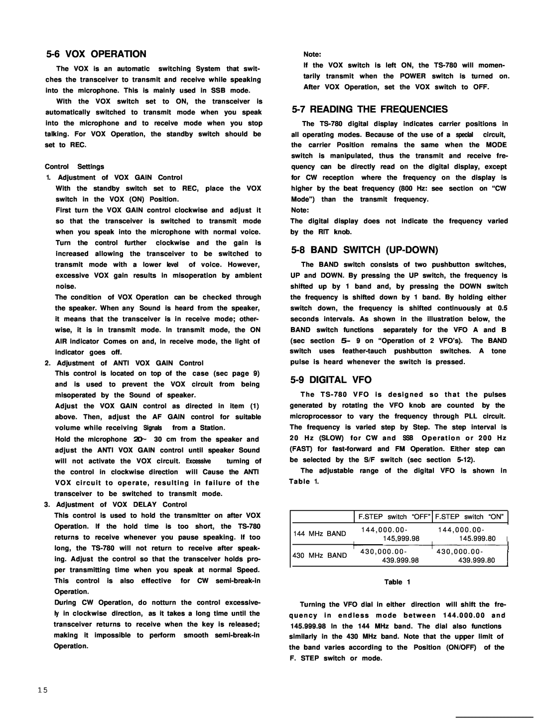
The adjustable range of the digital VFO is shown in Table 1.
|
| F.STEP switch “OFF” | F.STEP switch “ON” | |
|
|
|
|
|
| 144 MHz BAND | 1 4 4 , 0 0 0 . 0 0 - | 1 4 4 , 0 0 0 . 0 0 - | |
| 145,999.98 | 145.999.80 I | ||
|
| |||
|
|
|
|
|
| 430 MHz BAND | 4 3 0 , 0 0 0 . 0 0 - | 4 3 0 , 0 0 0 . 0 0 - | |
| 439.999.98 | 439.999.80 | ||
|
| |||
|
|
|
|
|
Table 1
Turning the VFO dial in either direction will shift the fre- quency in endless mode between 144 . 000 . 00 and 145.999.98 In the 144 MHz band. The dial also functions similarly in the 430 MHz band. Note that the upper limit of the band varies according to the Position (ON/OFF) of the F. STEP switch or mode.
1 5