Note:
The
Transmission
1.Set the MODE switch to USB and the meter switch to ALC/CEN. Other controls remain the same as outlined in section on “FM Mode”.
2.Adjust the microphone gain. This adjustment should be made with the standby switch set to SEND or the microphone PTT switch depressed.
Next, speak into the microphone and adjust the SSB
Mic gain control on the front Panel, making sure that the ALC meter does not deflect beyond the ALC zone. After completion of the above adjustment, set the meter switch to RF.
Note:
Periodically check the ALC meter deflection. lf, due to heat, etc., there iS a Change in deflection, reset the meter to within the ALC Zone.
Discrimination between SSB and FM 1. Use of S meter
If the S meter is steady (meter pointer almost Stops), the incoming Signal is FM; otherwise, it is SSB.
2.Use of MODE switch
If a clear Signal is heard at the FM Position of the MODE switch, the Signal is FM. The Sound in SSB mode is not heard at this Position.
Use of RIT Switch
For detailed information, refer to section on “FM Mode”. In SSB mode, if the receive frequency has drifted, set the RIT switch to ON and adjust the RIT knob, as in the case of FM mode.
When the RIT switch is ON, the receive frequency is off- set from the transmit frequency, so it is necessary to turn the switch off when tuning to another frequency.
Use of NB (noise blanker) Switch
The NB switch is used to suppress pulse noise such as ignition noise generated by car engine.
Use of RF GAIN Control
For detailed information, refer to section on “FM Mode” . Normally, this control should be left in full clockwise position. When a very strong incoming Signal is present, turn it counterclockwise. The noise level below the receive Signal level is attenuated for clear reception.
If the RF GAIN is reduced excessively in SSB or CW mode, the S meter deflection will increase irrespective of incoming Signal strength . This is due to the circuit characteristics and is not an indication of trouble.
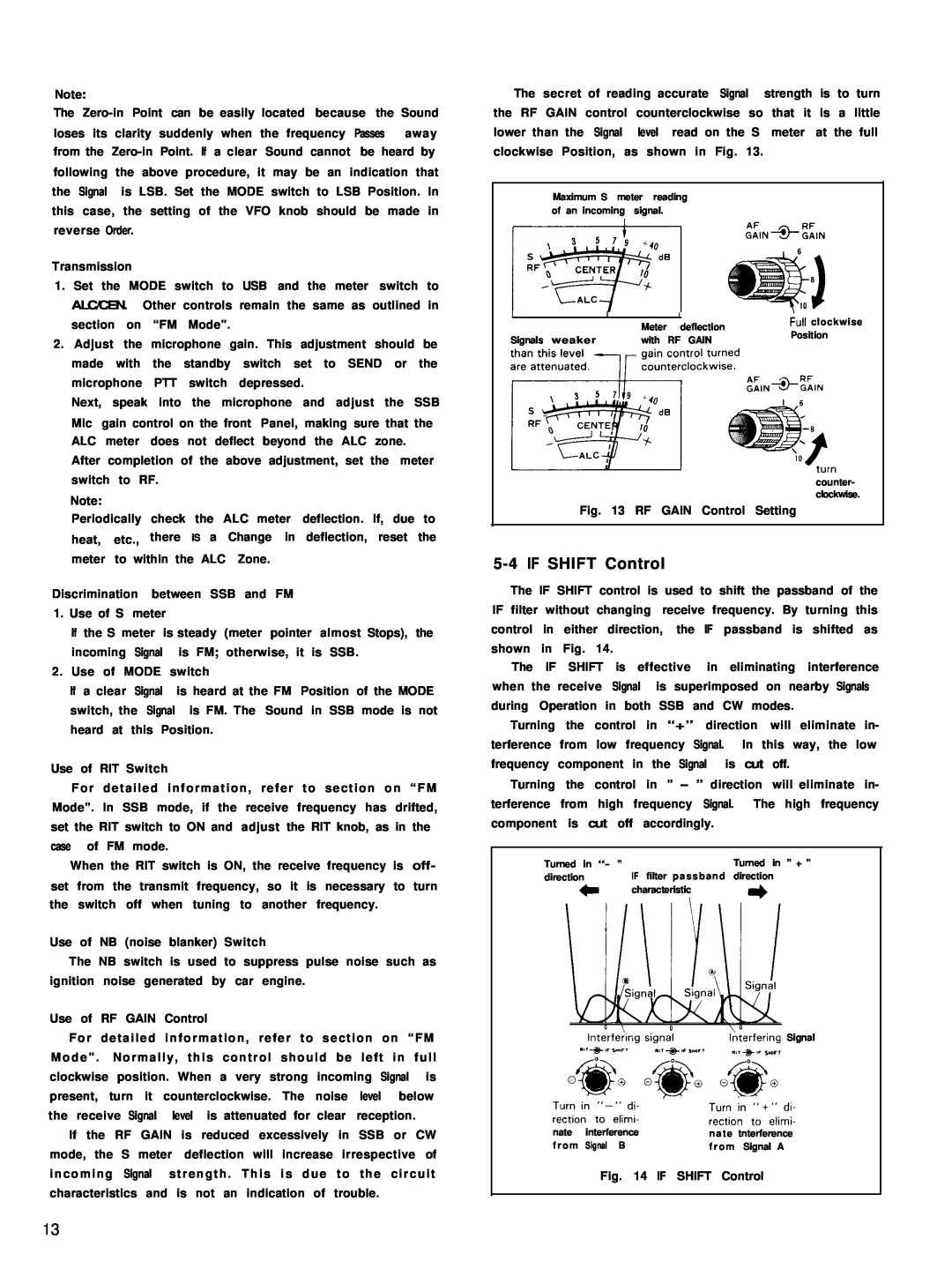
The secret of reading accurate Signal strength is to turn the RF GAIN control counterclockwise so that it is a little lower than the Signal level read on the S meter at the full clockwise Position, as shown in Fig. 13.
Maximum S meter reading of an incoming signal.
| I | I | hl clockwise | |
| Meter | deflection | ||
| Position | |||
Signals weaker | with | RF GAIN | ||
|
counter- clockwise.
Fig. 13 RF GAIN Control Setting
5-4 IF SHIFT Control
The IF SHIFT control is used to shift the passband of the IF filter without changing receive frequency. By turning this control in either direction, the IF passband is shifted as shown in Fig. 14.
The IF SHIFT is effective in eliminating interference when the receive Signal is superimposed on nearby Signals during Operation in both SSB and CW modes.
Turning the control in “+” direction will eliminate in- terference from low frequency Signal. In this way, the low frequency component in the Signal is cut off.
Turning the control in ” - ” direction will eliminate in- terference from high frequency Signal. The high frequency component is cut off accordingly.
Turned in “- ” |
| Turned in ” + ” |
direction | IF filter passband direction | |
c | characteristic | * |
| ||
I2erfering Signal ‘,‘+d I”WI
Teupo; | “n ;,+;;,v: | ||
nate | interference | nate | tnterference |
f r o m | Signal B | f r o m | Signal A |
Fig. 14 IF SHIFT Control
13