0 Adjustment (SWR)
Your antenna must be connected to a 50 ohms coaxial cable, since the antenna impedance of the
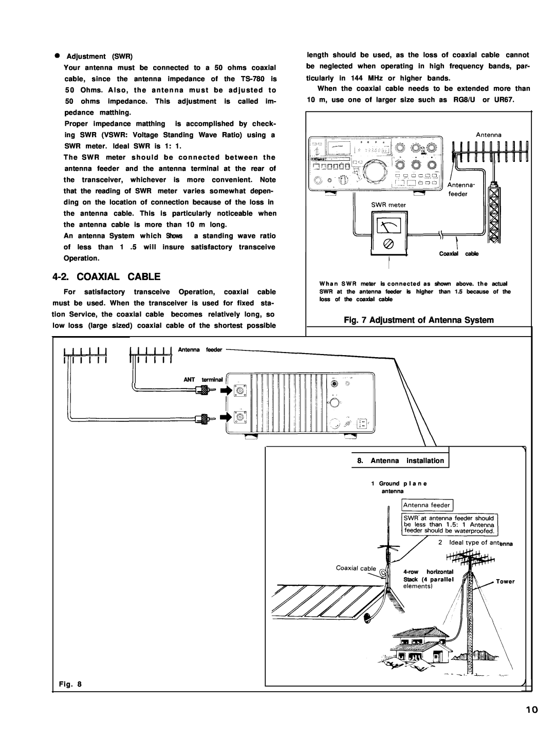
Proper impedance matthing is accomplished by check- ing SWR (VSWR: Voltage Standing Wave Ratio) using a SWR meter. Ideal SWR is 1: 1.
The SWR meter should be connected between the antenna feeder and the antenna terminal at the rear of the transceiver, whichever is more convenient. Note that the reading of SWR meter varies somewhat depen- ding on the location of connection because of the loss in the antenna cable. This is particularly noticeable when the antenna cable is more than 10 m long.
An antenna System which Shows a standing wave ratio of less than 1 .5 will insure satisfactory transceive Operation.
4-2. COAXIAL CABLE
For satisfactory transceive Operation, coaxial cable must be used. When the transceiver is used for fixed sta- tion Service, the coaxial cable becomes relatively long, so low loss (large sized) coaxial cable of the shortest possible
length should be used, as the loss of coaxial cable cannot be neglected when operating in high frequency bands, par- ticularly in 144 MHz or higher bands.
When the coaxial cable needs to be extended more than
10 m, use one of larger size such as RG8/U or UR67.
I | 1 | Coaxial cable |
’ ![]() t ’
t ’
W h a n S W R meter is connected as shown above. t h e actual SWR at the antenna feeder is higher than 1.5 because of the loss of the coaxial cable
Fig. 7 Adjustment of Antenna System
Antenna feeder
ANT terminal
8. Antenna installation
1 Ground p l a n e antenna
|
| enna |
horizontal |
| |
Stack | (4 parallel | Tower |
|
|
Fig. 8
