5-20 OSCAR OPERATION
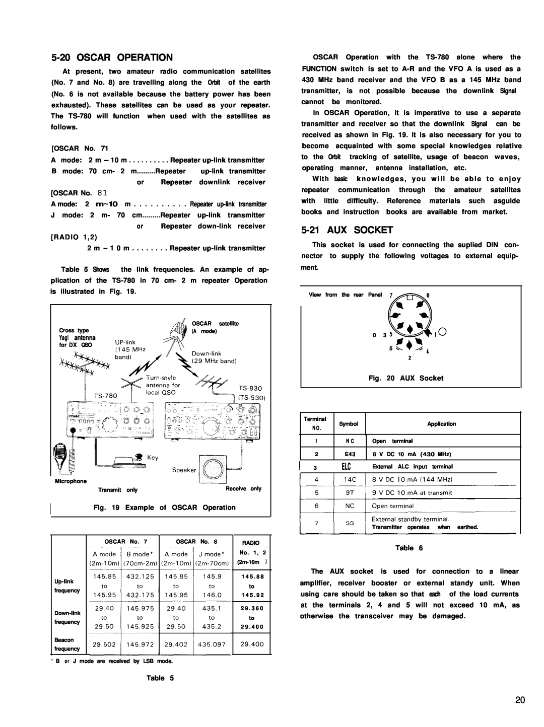
At present, two amateur radio communication satellites (No. 7 and No. 8) are travelling along the Orbit of the earth (No. 6 is not available because the battery power has been exhausted). These satellites can be used as your repeater. The
[OSCAR No. 71
Amode: 2 m - 10 m . . . . . . . . . . Repeater
B mode: 70 cm- 2 m.........Repeater
or Repeater downlink receiver
[OSCAR No. 81
A mode: 2 m~10 m . . . . . . . . . . Repeater
Jmode: 2 m- 70 cm.........Repeater
or Repeater
[RADIO 1,2)
2 m - 1 0 m . . . . . . . . Repeater
Table 5 Shows the link frequencies. An example of ap- plication of the
|
| OSCAR satellite |
Cross | type | (A mode) |
Yagi | antenna |
|
for DX QSO
Microphone |
|
|
|
| ||
|
| Transmit | only |
| Receive only | |
|
| Fig. 19 Example of OSCAR Operation | ||||
|
|
|
|
|
|
|
|
|
|
|
|
|
|
|
| OSCAR | No. 7 | OSCAR No. 8 |
| RADIO |
|
|
|
|
|
| No. 1, 2 |
|
|
|
|
|
| |
|
|
|
|
|
|
|
|
|
|
|
| 1 4 5 . 8 8 | |
|
|
|
|
| to | |
frequency |
|
|
|
|
| |
|
|
|
|
| 1 4 5 . 9 2 | |
|
|
|
|
|
| |
|
|
|
|
|
|
|
|
|
|
|
| 2 9 . 3 6 0 | |
|
|
|
|
| to | |
frequency |
|
|
|
|
| |
|
|
|
|
| 2 9 . 4 0 0 | |
|
|
|
|
|
| |
Beacon |
|
|
|
|
|
|
|
|
|
|
|
| |
frequency |
|
|
|
|
|
|
|
|
|
|
|
|
|
* B or J mode are received by LSB mode.
Table 5
OSCAR Operation with the
In OSCAR Operation, it is imperative to use a separate transmitter and receiver so that the downlink Signal can be received as shown in Fig. 19. lt is also necessary for you to become acquainted with some special knowledges relative to the Orbit tracking of satellite, usage of beacon waves, operating manner, antenna installation, etc.
With basic knowledges, you will be able to enjoy repeater communication through the amateur satellites with little difficulty. Reference materials such asguide books and instruction books are available from market.
5-21 AUX SOCKET
This socket is used for connecting the suplied DIN con- nector to supply the following voltages to external equip- ment.
View from the rear Panel Cl
7 R Ib
0 3* 10
59’ 4 2
Fig. 20 AUX Socket
| Terminal |
| Symbol | Application | |
| N O . |
| |||
|
|
|
|
| |
|
|
|
|
|
|
| 1 |
| N C | Open terminal | |
|
| ||||
|
|
|
|
|
|
| 2 |
| E43 | 8 V DC 10 mA (430 MHz) | |
|
|
|
|
|
|
1 3 | / | ELC | t Extemal ALC input terminal | ||
|
|
|
|
|
|
Transmitter operates when earthed.
Table 6
The AUX socket is used for connection to a linear amplifier, receiver booster or external standy unit. When using care should be taken so that each of the load currents at the terminals 2, 4 and 5 will not exceed 10 mA, as otherwise the transceiver may be damaged.
20