
08WXRC, WXRC specifications
The Kicker WXRC and 08WXRC series represent a blend of innovative audio engineering and rugged design, tailored specifically for passionate car audio enthusiasts. These subwoofers are designed to deliver deep, resonant bass that can transform any vehicle into a mobile sound stage.One of the main features of the Kicker WXRC subwoofers is their custom, high-output woofer cone. Constructed with a durable injection-molded polypropylene, the cone not only ensures longevity but also enhances the clarity and punch of the sound produced. This design minimizes distortion and allows for a more powerful low-frequency output, providing listeners with the immersive experience they crave.
The technology behind the Kicker WXRC includes a high-temperature voice coil, which allows the subwoofers to handle increased power levels without overheating. This is crucial for users who enjoy playing their audio at loud levels, as it ensures reliability and performance throughout extended listening sessions. The dual voice coil configuration offers flexible wiring options, allowing the subwoofers to be easily integrated into various audio setups.
Another notable characteristic of the Kicker WXRC series is its robust enclosure design. The subwoofers are engineered to work optimally in a variety of enclosure types, including sealed or ported configurations, making them versatile for different sound preferences. The enclosures are often constructed with high-grade MDF for added durability and reduced resonance, ensuring that the sound remains clean and powerful.
The Kicker WXRC and 08WXRC subwoofers are also equipped with advanced cooling technologies. Their unique venting system allows air to flow freely over the voice coil, reducing the risk of thermal build-up during intense play. This means that users can enjoy high volumes without compromising the quality of their audio.
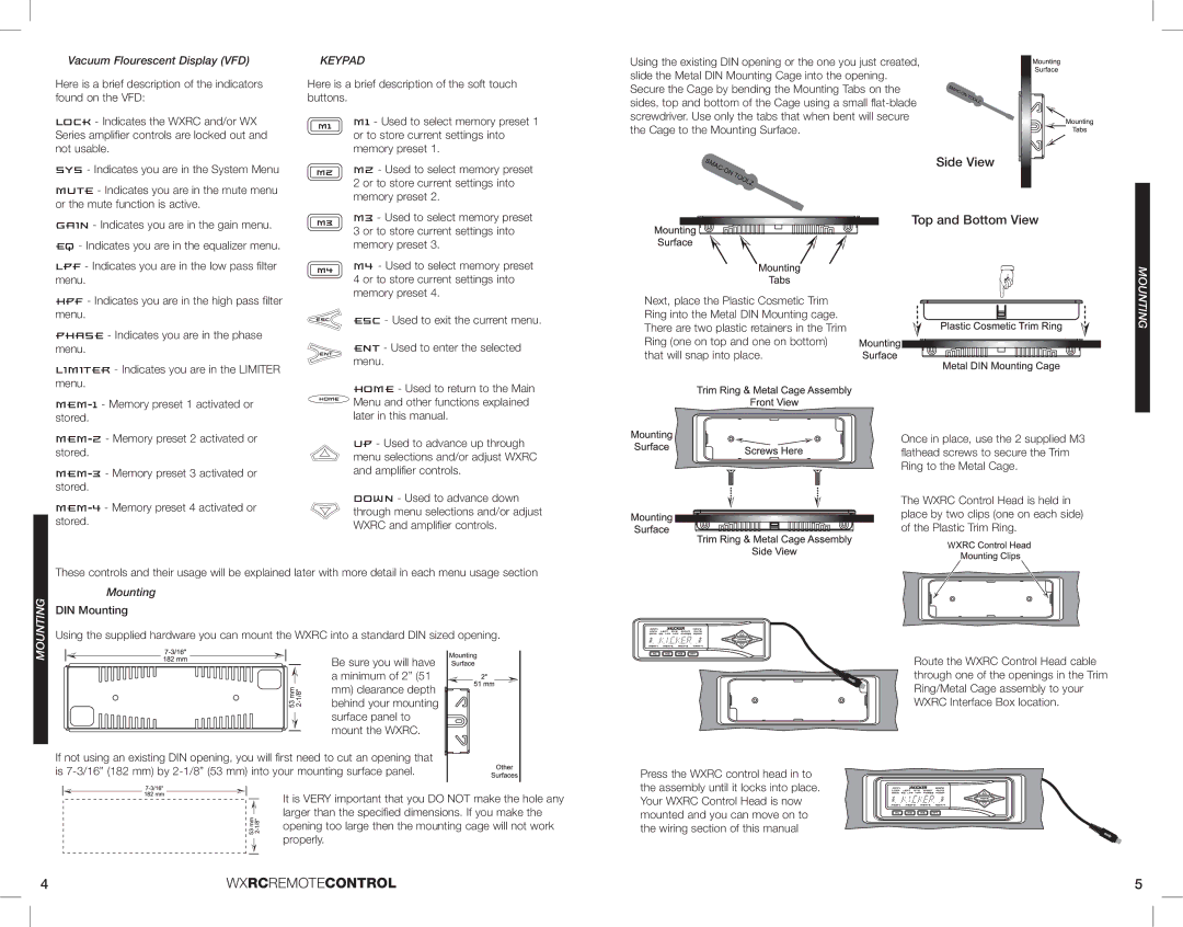
In terms of installation, the Kicker WXRC subwoofers come with a variety of mounting options, ensuring compatibility with a wide range of vehicles. Their sleek design and customizable features make them an attractive choice for anyone looking to upgrade their sound system.
Overall, the Kicker WXRC and 08WXRC subwoofers are designed to deliver exceptional bass performance in a reliable, robust package. With their impressive features, advanced technologies, and commitment to sound quality, these subwoofers stand out as a top choice for car audio enthusiasts seeking to elevate their listening experience.