DY11 7HJ specifications
Klark Teknik has long been synonymous with excellence in audio processing and dynamic control, and the DY11 7HJ is no exception. This versatile digital processor caters to audio engineers, musicians, and production professionals, delivering superior sound quality and innovative features that enhance any audio setup.One of the standout characteristics of the DY11 7HJ is its compact design, making it ideal for various applications, from live performances to studio recording. Despite its small footprint, it boasts a powerful digital signal processing (DSP) engine that supports advanced algorithms for dynamic range management and sound shaping. This ensures that users can achieve the desired sound profile effortlessly and efficiently.
The DY11 7HJ features an intuitive user interface that allows for swift adjustments and deep customization. With its smooth navigation and clear display, engineers can quickly adapt settings in real-time during performances or recordings. Users have access to an array of presets specifically designed for various instruments, vocal types, and genres, making it easy to find the perfect sound without needing detailed technical knowledge.
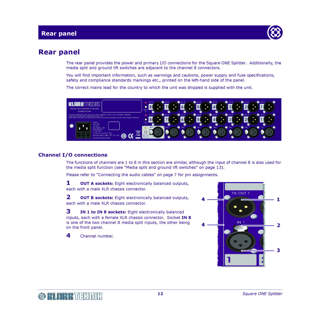
Connectivity is another strong point of the DY11 7HJ, offering multiple input and output options. It supports both analog and digital connections, facilitating integration with other audio equipment. This versatility enhances workflow in both live and studio environments, allowing seamless interaction with mixers, effects processors, and recording devices.
In terms of sound processing, the DY11 7HJ utilizes cutting-edge compression and gating technologies. These features enable precise control over dynamics, ensuring that audio signals are balanced and clear, whether addressing vocal tracks or handling dynamic instrumental performances. Moreover, the integrated equalization capabilities allow for real-time adjustments to shape the audio tone, making it easier to fit each sound into the larger mix.
Durability and reliability are also key characteristics of the DY11 7HJ. Constructed with high-quality materials, it is designed to withstand the rigors of live performance and studio use, ensuring longevity and consistent performance.
In conclusion, the Klark Teknik DY11 7HJ stands out as a remarkable digital audio processor, equipped with powerful features, advanced technologies, and robust connectivity options. Whether you are a seasoned audio professional or a budding enthusiast, the DY11 7HJ is engineered to enhance your sound experience, making it a valuable tool in any audio arsenal. With its impressive performance and user-friendly interface, this processor is set to meet the demands of modern audio production and live sound environments.

