2
1
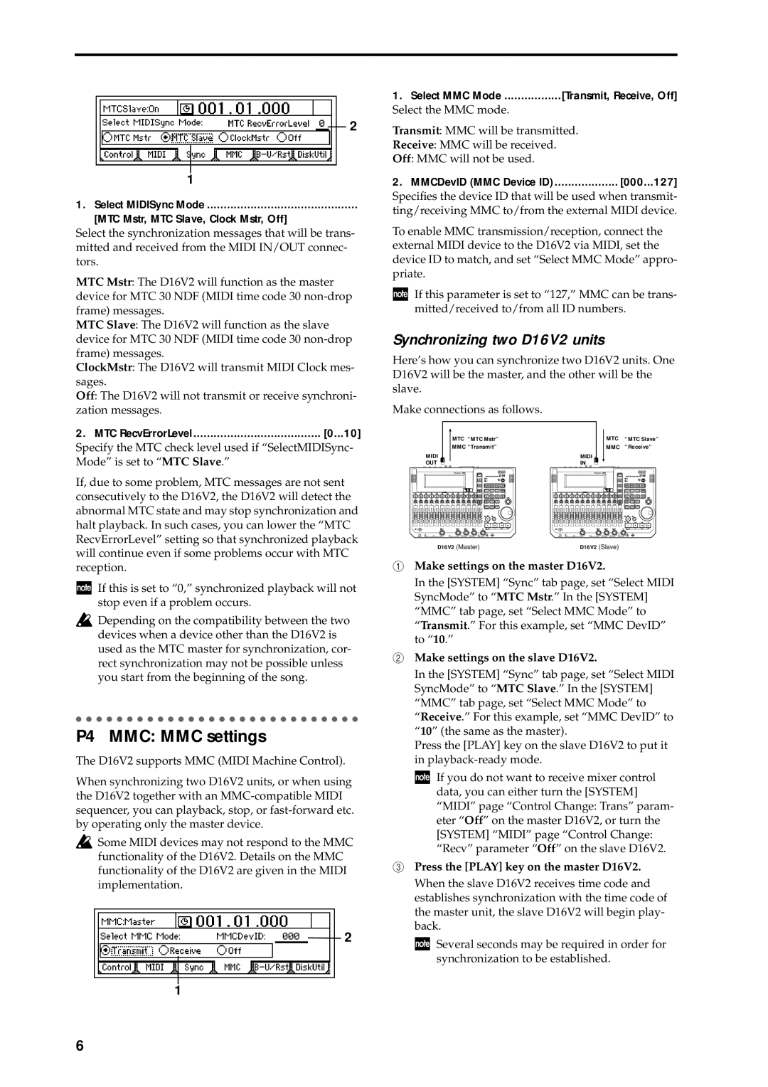
1.Select MIDISync Mode .............................................
[MTC Mstr, MTC Slave, Clock Mstr, Off]
Select the synchronization messages that will be trans- mitted and received from the MIDI IN/OUT connec- tors.
MTC Mstr: The D16V2 will function as the master device for MTC 30 NDF (MIDI time code 30
MTC Slave: The D16V2 will function as the slave device for MTC 30 NDF (MIDI time code 30
ClockMstr: The D16V2 will transmit MIDI Clock mes- sages.
Off: The D16V2 will not transmit or receive synchroni- zation messages.
2.MTC RecvErrorLevel ...................................... [0...10]
Specify the MTC check level used if “SelectMIDISync- Mode” is set to “MTC Slave.”
If, due to some problem, MTC messages are not sent consecutively to the D16V2, the D16V2 will detect the abnormal MTC state and may stop synchronization and halt playback. In such cases, you can lower the “MTC RecvErrorLevel” setting so that synchronized playback will continue even if some problems occur with MTC reception.
If this is set to “0,” synchronized playback will not stop even if a problem occurs.
![]() Depending on the compatibility between the two devices when a device other than the D16V2 is used as the MTC master for synchronization, cor- rect synchronization may not be possible unless you start from the beginning of the song.
Depending on the compatibility between the two devices when a device other than the D16V2 is used as the MTC master for synchronization, cor- rect synchronization may not be possible unless you start from the beginning of the song.
P4 MMC: MMC settings
The D16V2 supports MMC (MIDI Machine Control).
When synchronizing two D16V2 units, or when using the D16V2 together with an
![]() Some MIDI devices may not respond to the MMC functionality of the D16V2. Details on the MMC functionality of the D16V2 are given in the MIDI implementation.
Some MIDI devices may not respond to the MMC functionality of the D16V2. Details on the MMC functionality of the D16V2 are given in the MIDI implementation.
2
1
1.Select MMC Mode .................[Transmit, Receive, Off]
Select the MMC mode.
Transmit: MMC will be transmitted.
Receive: MMC will be received.
Off: MMC will not be used.
2.MMCDevID (MMC Device ID) ................... [000...127]
Specifies the device ID that will be used when transmit- ting/receiving MMC to/from the external MIDI device.
To enable MMC transmission/reception, connect the external MIDI device to the D16V2 via MIDI, set the device ID to match, and set “Select MMC Mode” appro- priate.
If this parameter is set to “127,” MMC can be trans- mitted/received to/from all ID numbers.
Synchronizing two D16V2 units
Here’s how you can synchronize two D16V2 units. One D16V2 will be the master, and the other will be the slave.
Make connections as follows.
|
| MTC “MTC Mstr” |
|
|
| MTC | “MTC Slave” | |||
|
|
|
|
| ||||||
|
| MMC “Transmit” |
|
|
| MMC | “Receive” | |||
MIDI |
|
|
|
| MIDI |
|
|
|
|
|
OUT |
|
|
|
| IN |
|
|
|
| |
D16V2 (Master) | D16V2 (Slave) |
1Make settings on the master D16V2.
In the [SYSTEM] “Sync” tab page, set “Select MIDI SyncMode” to “MTC Mstr.” In the [SYSTEM] “MMC” tab page, set “Select MMC Mode” to “Transmit.” For this example, set “MMC DevID” to “10.”
2Make settings on the slave D16V2.
In the [SYSTEM] “Sync” tab page, set “Select MIDI SyncMode” to “MTC Slave.” In the [SYSTEM] “MMC” tab page, set “Select MMC Mode” to “Receive.” For this example, set “MMC DevID” to “10” (the same as the master).
Press the [PLAY] key on the slave D16V2 to put it in
![]() If you do not want to receive mixer control data, you can either turn the [SYSTEM] “MIDI” page “Control Change: Trans” param- eter “Off” on the master D16V2, or turn the [SYSTEM] “MIDI” page “Control Change: “Recv” parameter “Off” on the slave D16V2.
If you do not want to receive mixer control data, you can either turn the [SYSTEM] “MIDI” page “Control Change: Trans” param- eter “Off” on the master D16V2, or turn the [SYSTEM] “MIDI” page “Control Change: “Recv” parameter “Off” on the slave D16V2.
3Press the [PLAY] key on the master D16V2. When the slave D16V2 receives time code and establishes synchronization with the time code of the master unit, the slave D16V2 will begin play- back.
![]() Several seconds may be required in order for synchronization to be established.
Several seconds may be required in order for synchronization to be established.
6