Kramer Electronics vs-48hdcpx1 user manual Kramer Protocol, Machine Number

Models: vs-48hdcpx1

1 30
Download 30 pages 57 Kb
Page 26
Image 26

9 Kramer Protocol 2000

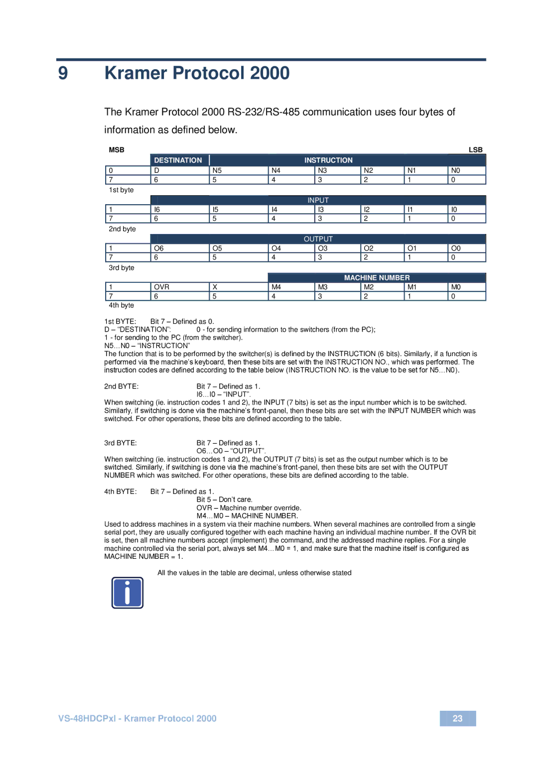
The Kramer Protocol 2000 RS-232/RS-485 communication uses four bytes of information as defined below.

MSB


LSB


DESTINATION


INSTRUCTION


0

D


N5

N4


N3


N2

N1

N0

7

6


5

4


3


2

1

0

1st byte


INPUT


1

I6


I5

I4


I3


I2

I1

I0

7

6


5

4


3


2

1

0

2nd byte


OUTPUT


1

O6


O5

O4


O3


O2

O1

O0

7

6


5

4


3


2

1

0

3rd byte


MACHINE NUMBER


1

OVR


X

M4


M3


M2

M1

M0

7

6


5

4


3


2

1

0

4th byte


1st BYTE:

Bit 7 – Defined as 0.


D – “DESTINATION”:

0 - for sending information to the switchers (from the PC);


1 - for sending to the PC (from the switcher).


N5…N0 – “INSTRUCTION”

The function that is to be performed by the switcher(s) is defined by the INSTRUCTION (6 bits). Similarly, if a function is performed via the machine’s keyboard, then these bits are set with the INSTRUCTION NO., which was performed. The instruction codes are defined according to the table below (INSTRUCTION NO. is the value to be set for N5…N0).

2nd BYTE:

Bit 7 – Defined as 1.


I6…I0 – “INPUT”.

When switching (ie. instruction codes 1 and 2), the INPUT (7 bits) is set as the input number which is to be switched. Similarly, if switching is done via the machine’s front-panel, then these bits are set with the INPUT NUMBER which was switched. For other operations, these bits are defined according to the table.

3rd BYTE:

Bit 7 – Defined as 1.


O6…O0 – “OUTPUT”.

When switching (ie. instruction codes 1 and 2), the OUTPUT (7 bits) is set as the output number which is to be switched. Similarly, if switching is done via the machine’s front-panel, then these bits are set with the OUTPUT NUMBER which was switched. For other operations, these bits are defined according to the table.

4th BYTE: Bit 7 – Defined as 1.

Bit 5 – Don’t care.

OVR – Machine number override. M4…M0 – MACHINE NUMBER.

Used to address machines in a system via their machine numbers. When several machines are controlled from a single serial port, they are usually configured together with each machine having an individual machine number. If the OVR bit is set, then all machine numbers accept (implement) the command, and the addressed machine replies. For a single machine controlled via the serial port, always set M4…M0 = 1, and make sure that the machine itself is configured as

MACHINE NUMBER = 1.

i

All the values in the table are decimal, unless otherwise stated

VS-48HDCPxl - Kramer Protocol 2000

23


Page 26
Image 26
Kramer Electronics vs-48hdcpx1 user manual Kramer Protocol, Machine Number

vs-48hdcpx1 specifications

Kramer Electronics' vs-48hdcpx1 is a versatile and powerful matrix switcher designed to streamline video signal management in professional AV applications. This model specifically caters to the growing demand for high-definition video switching, focusing on the efficient handling of HDMI signals.

One of the key features of the vs-48hdcpx1 is its ability to switch up to 48 HDMI sources to 48 separate displays, allowing users to manage a large number of input and output devices from a single unit. This functionality is particularly beneficial in environments such as conference rooms, educational institutions, and large venues where multiple displays are needed.

The vs-48hdcpx1 supports resolutions up to 4K at 60Hz, ensuring that high-definition content is transmitted without quality loss. This capability is crucial for modern video applications where clarity and detail are paramount. Additionally, the switcher supports various video formats, catering to a wide range of input devices.

One of the standout technologies incorporated into the vs-48hdcpx1 is its EDID (Extended Display Identification Data) management, which simplifies the communication between connected devices. This feature enhances compatibility and ensures that all devices recognize available display resolutions and capabilities, resulting in a seamless operation.

The unit also supports HDCP (High-bandwidth Digital Content Protection), which is essential for transmitting protected content. This compliance guarantees that users can enjoy premium video without interruptions due to copyright issues.

In terms of usability, the vs-48hdcpx1 offers multiple control options. It can be managed through the front panel buttons, remote control, or an optional control app, making it convenient for users with different technical expertise levels. Additionally, the device supports RS-232 and TCP/IP for integration into existing control systems.

Another notable characteristic is its robust design, built for reliability and longevity in demanding environments. The unit is housed in a sturdy chassis that prevents damage from impacts or vibrations, thus maintaining functionality even in high-traffic areas.

Kramer Electronics also emphasizes easy installation with the vs-48hdcpx1, providing comprehensive documentation and support. This commitment to user-friendliness ensures that installations can be completed efficiently, minimizing downtime.

In summary, the Kramer Electronics vs-48hdcpx1 matrix switcher distinguishes itself with high-capacity switching capabilities, 4K resolution support, advanced EDID management, HDCP compliance, and flexible control options. Its rugged design and focus on ease of use make it an ideal choice for any professional AV setup looking to maximize video signal management.