INSTALLATION REQUIREMENTS
2.3.3.1Running Cables
Cables should only be installed by qualified personnel who are familiar with the electrical requirements and safety precautions that are necessary to properly and safely install (run) these items.
The cables should be inspected prior to installation. Connectors should be visually inspected prior to connecting to their mating connector.
2.3.3.2V750 Cable and Connector Requirements
The V750 cable and connector requirements are as follows:
•Cabling consisting of four (4) wires will be required between the V750 and the pan/tilt for azimuth and elevation feedback.
—Some pan/tilts may already have the potentiometers installed in which case the wires needed may already be terminated and run through the NYCOIL.
•The harness for the GPS/IMU can be extended to reach the roof of the vehicle if necessary.
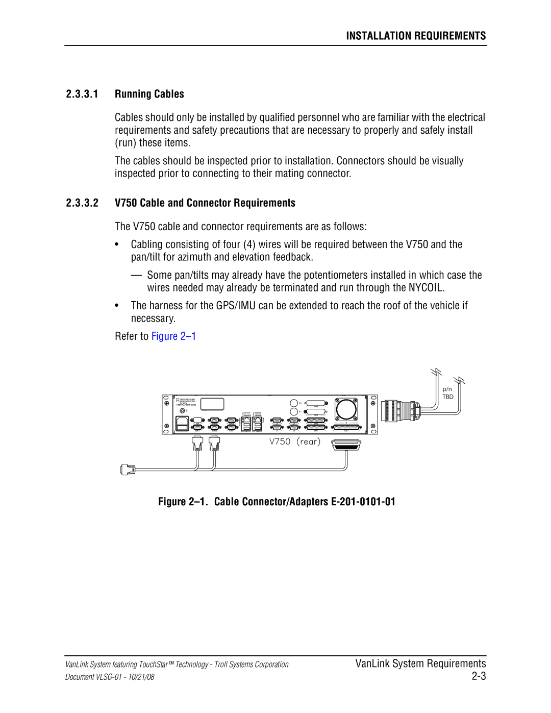
Refer to Figure 2–1
p/n
TBD
Figure 2–1. Cable Connector/Adapters E-201-0101-01
VanLink System featuring TouchStar™ Technology - Troll Systems Corporation
Document
VanLink System Requirements