INSTALLATION REQUIREMENTS
2.3.3.3Pan and Tilt Cabling and Connector Requirements
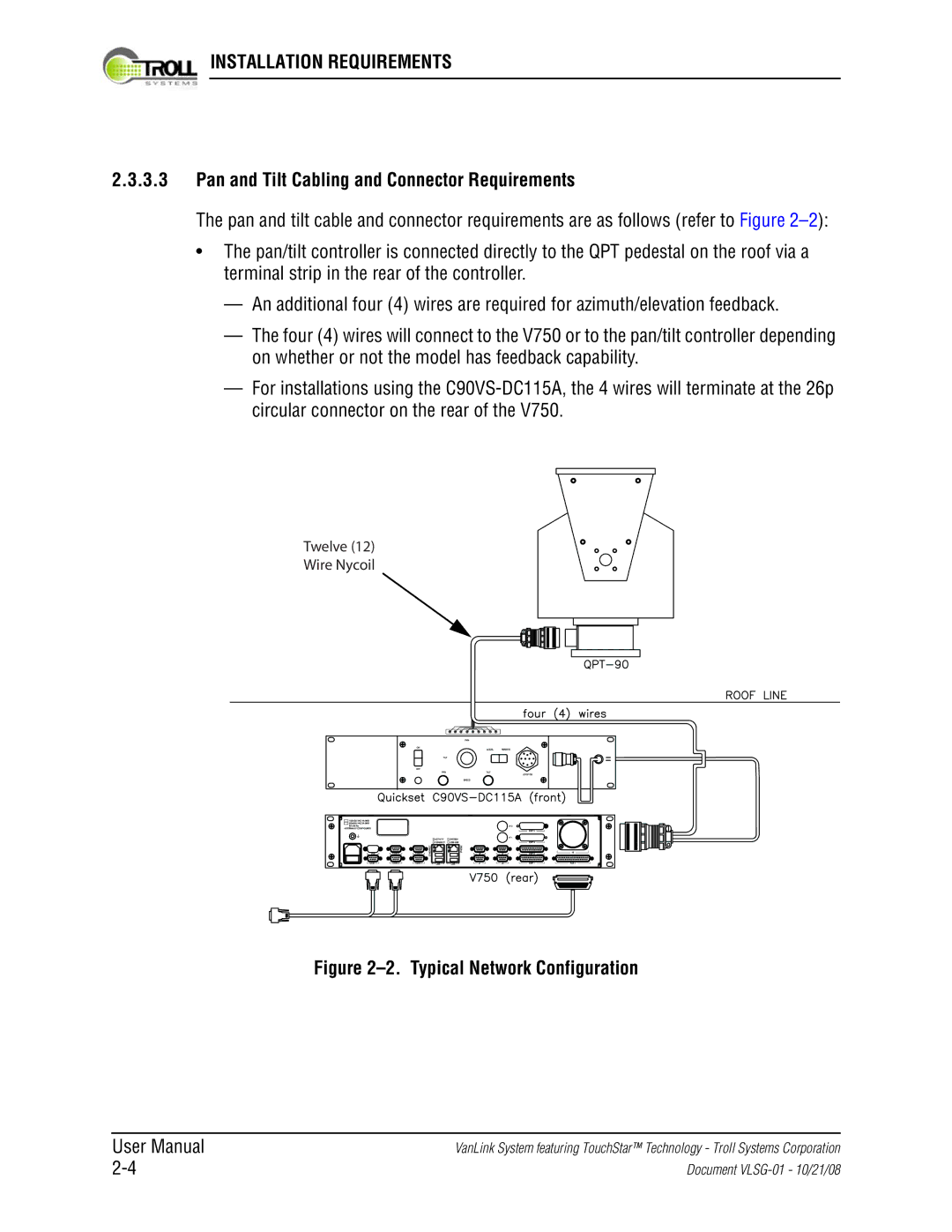
The pan and tilt cable and connector requirements are as follows (refer to Figure
•The pan/tilt controller is connected directly to the QPT pedestal on the roof via a terminal strip in the rear of the controller.
—An additional four (4) wires are required for azimuth/elevation feedback.
—The four (4) wires will connect to the V750 or to the pan/tilt controller depending on whether or not the model has feedback capability.
—For installations using the
Twelve (12)
Wire Nycoil
Figure 2–2. Typical Network Configuration
User Manual
VanLink System featuring TouchStar™ Technology - Troll Systems Corporation
Document