LOADING
PRODUCTS: fill the canisters with the products.
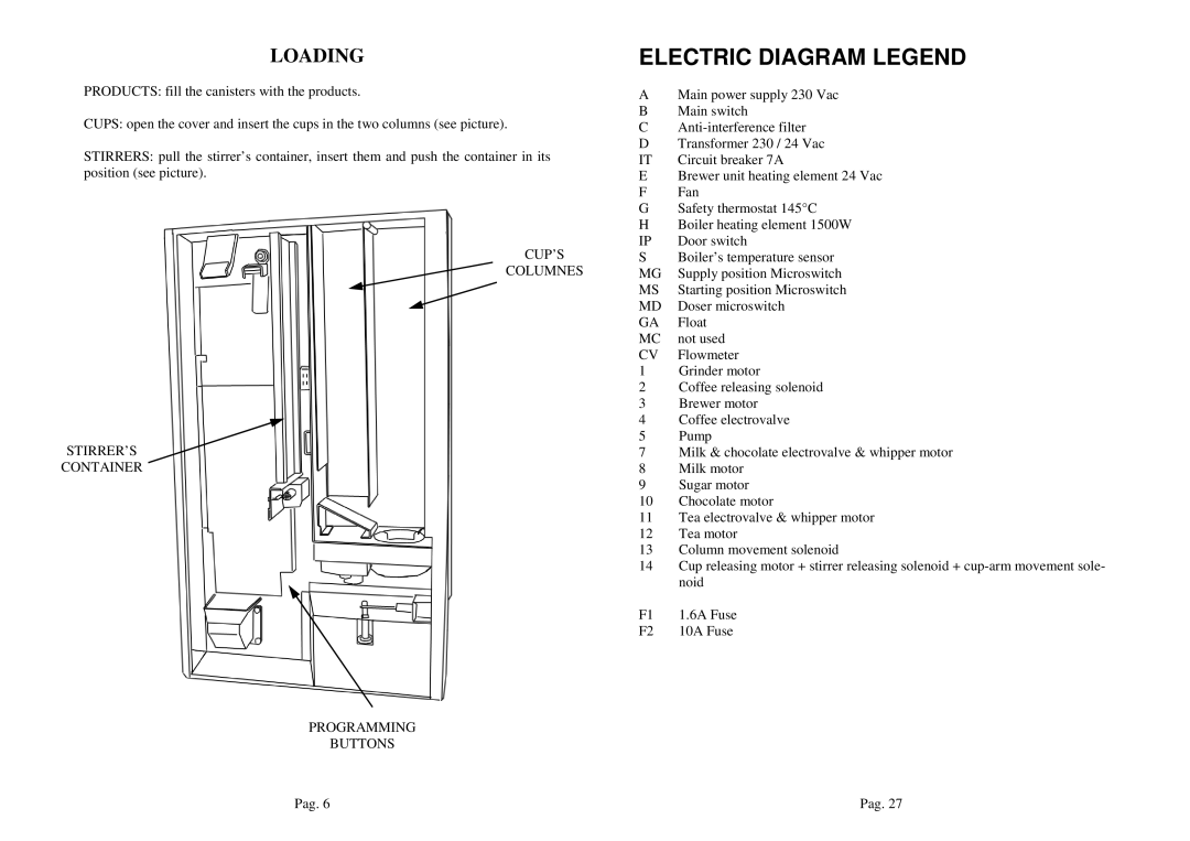
CUPS: open the cover and insert the cups in the two columns (see picture).
STIRRERS: pull the stirrer’s container, insert them and push the container in its position (see picture).
CUP’S
COLUMNES
STIRRER’S
CONTAINER
PROGRAMMING
BUTTONS
ELECTRIC DIAGRAM LEGEND
AMain power supply 230 Vac
BMain switch
C
DTransformer 230 / 24 Vac
IT Circuit breaker 7A
EBrewer unit heating element 24 Vac
FFan
GSafety thermostat 145°C
HBoiler heating element 1500W
IP | Door switch |
S | Boiler’s temperature sensor |
MG | Supply position Microswitch |
MS | Starting position Microswitch |
MD | Doser microswitch |
GA | Float |
MC | not used |
CV | Flowmeter |
1Grinder motor
2Coffee releasing solenoid
3Brewer motor
4Coffee electrovalve
5Pump
7Milk & chocolate electrovalve & whipper motor
8Milk motor
9Sugar motor
10Chocolate motor
11Tea electrovalve & whipper motor
12Tea motor
13Column movement solenoid
14Cup releasing motor + stirrer releasing solenoid +
F1 1.6A Fuse
F2 10A Fuse
Pag. 6 | Pag. 27 |