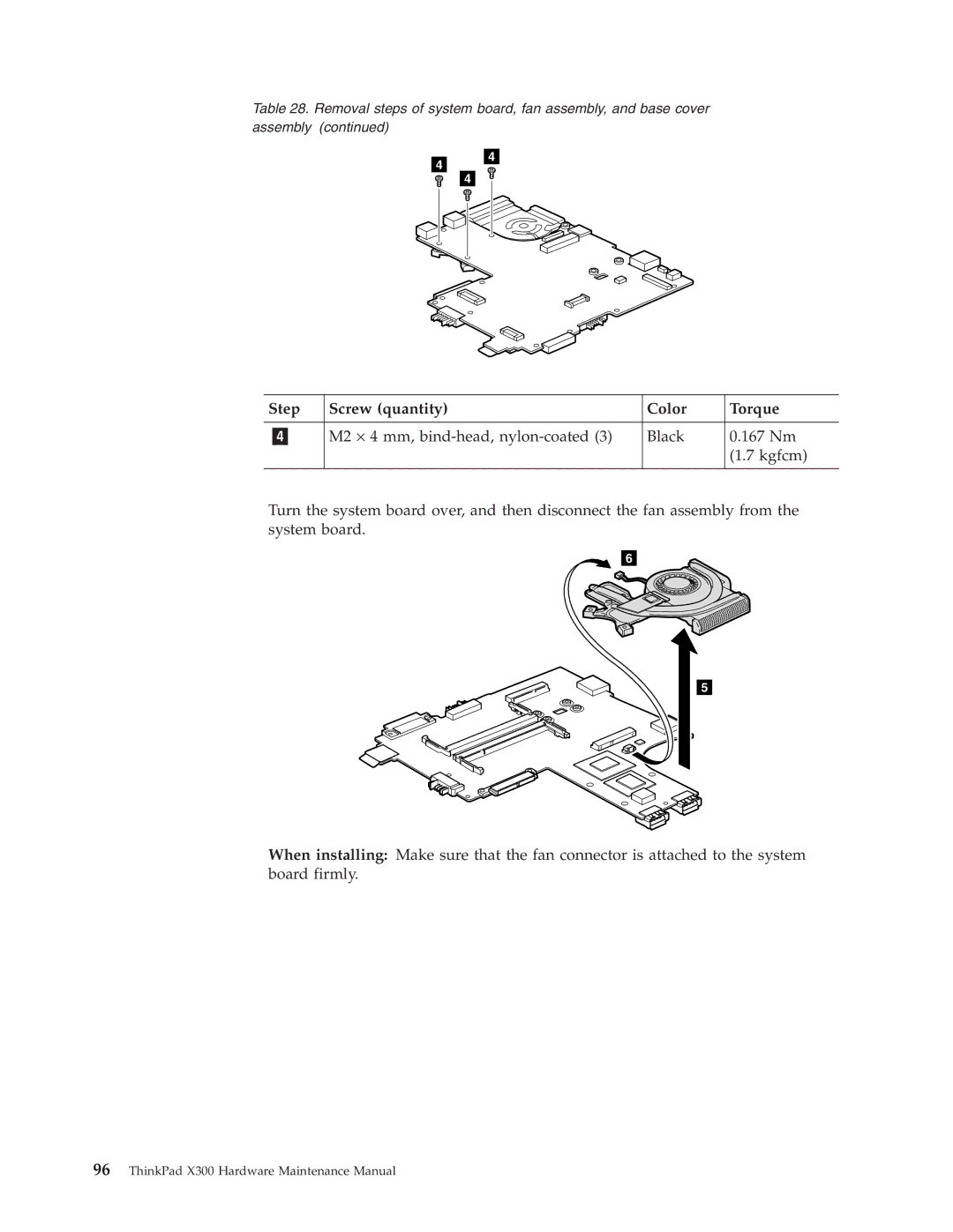
Table 28. Removal steps of system board, fan assembly, and base cover assembly (continued)
Step | Screw (quantity) | Color | Torque |
|
|
|
|
| M2 × 4 mm, | Black | 0.167 Nm |
|
|
| (1.7 kgfcm) |
|
|
|
|
Turn the system board over, and then disconnect the fan assembly from the system board.
6
5
When installing: Make sure that the fan connector is attached to the system board firmly.