2.1.2 CONTROL BOX (Half-Disassembly)
1.Remove the front grille. (Refer to section 2.1.1)
2.Remove the three screw which fasten the control
| box. (See Fig. 2) |
|
3. | Pull the control box from the barrier. (See Fig.2) |
|
4. | Discharge the capacitor by placing a 20,000 ohm |
|
| resistor across the capacitor terminals. |
|
5. | Disconnect three wire housings in the control box. |
|
6. | Pull the control box forward completely. |
|
7. |
| |
| removal procedure. (See Fig. 2) |
|
| (Refer to the circuit diagram found on page 25 in | Figure 2 |
| this manual and on the control box.) |
|
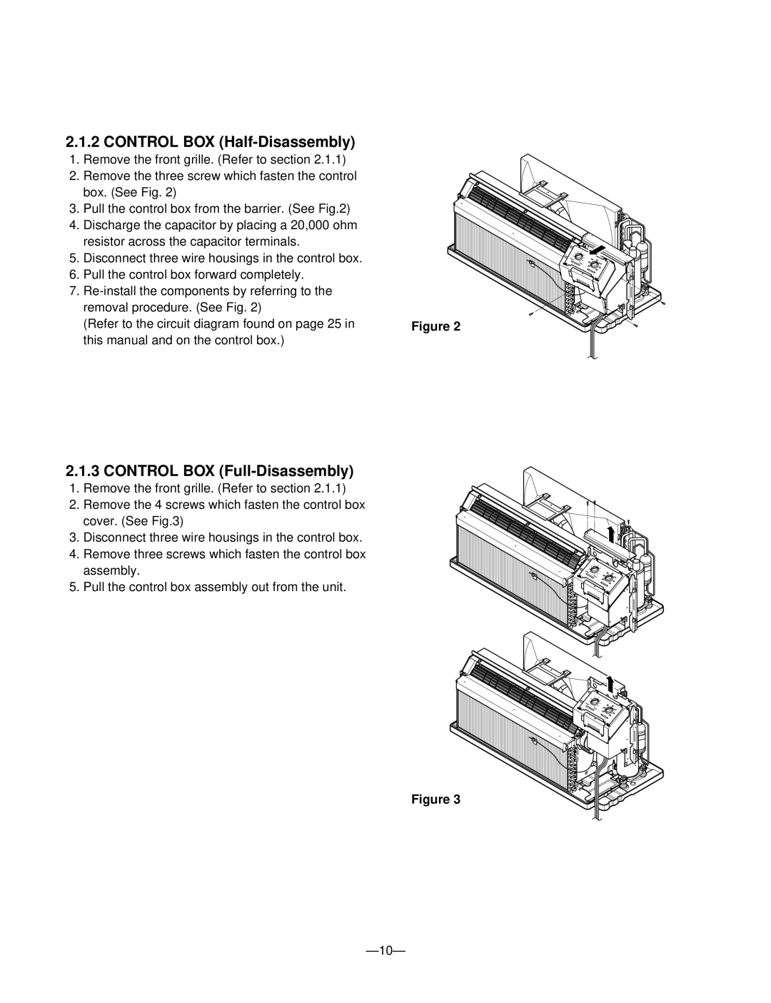
2.1.3 CONTROL BOX (Full-Disassembly)
1. Remove the front grille. (Refer to section 2.1.1)
2. Remove the 4 screws which fasten the control box cover. (See Fig.3)
3. Disconnect three wire housings in the control box.
4. Remove three screws which fasten the control box assembly.
5. Pull the control box assembly out from the unit.
Figure 3