2.2.3 SHROUD
1.Remove the fan. (Refer to section 2.2.2)
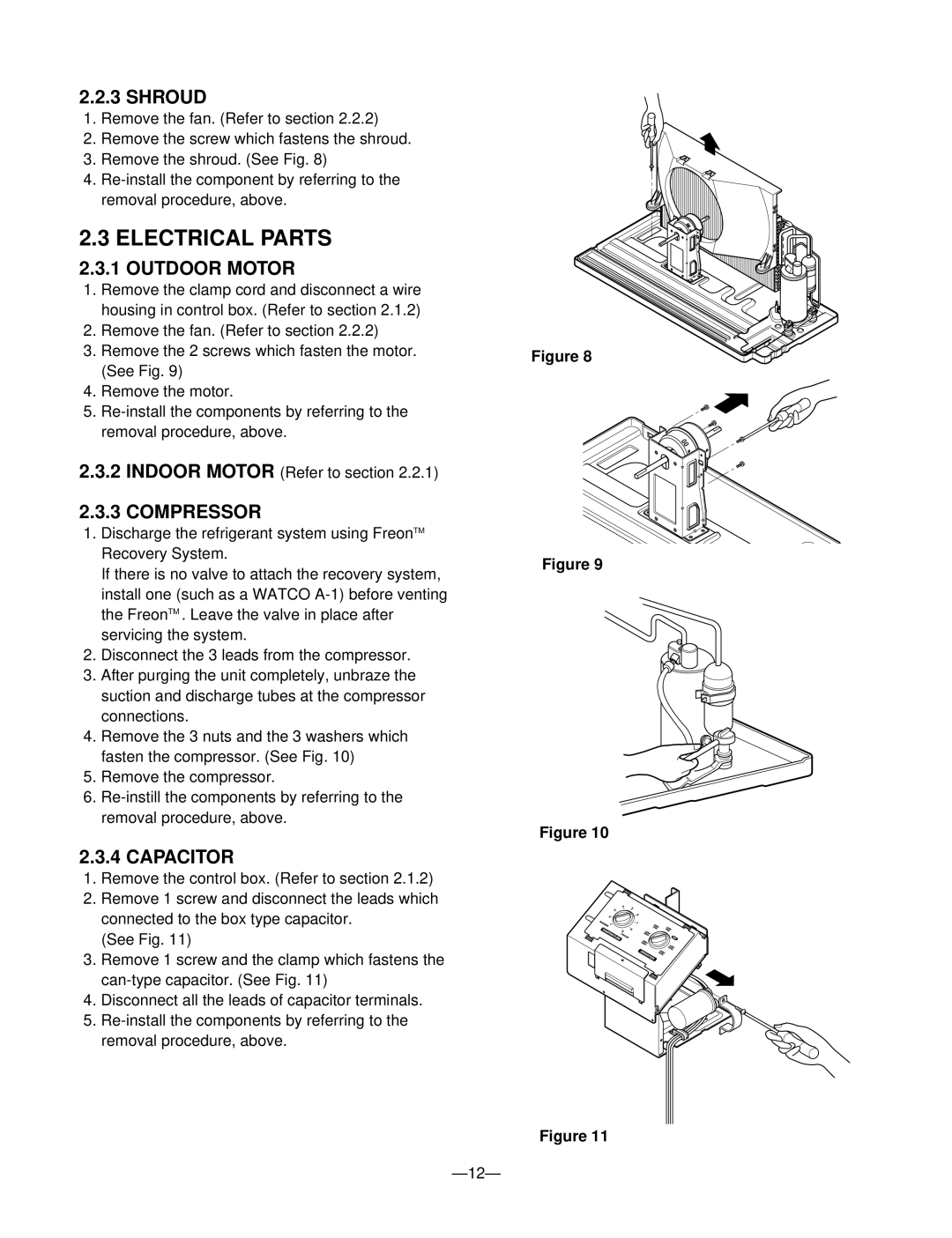
2.Remove the screw which fastens the shroud.
3.Remove the shroud. (See Fig. 8)
4.
2.3 ELECTRICAL PARTS
2.3.1 OUTDOOR MOTOR
1.Remove the clamp cord and disconnect a wire housing in control box. (Refer to section 2.1.2)
2.Remove the fan. (Refer to section 2.2.2)
3.Remove the 2 screws which fasten the motor. (See Fig. 9)
4.Remove the motor.
5.
2.3.2INDOOR MOTOR (Refer to section 2.2.1)
2.3.3COMPRESSOR
1.Discharge the refrigerant system using FreonTM Recovery System.
If there is no valve to attach the recovery system, install one (such as a WATCO
2.Disconnect the 3 leads from the compressor.
3.After purging the unit completely, unbraze the suction and discharge tubes at the compressor connections.
4.Remove the 3 nuts and the 3 washers which fasten the compressor. (See Fig. 10)
5.Remove the compressor.
6.
2.3.4 CAPACITOR
1.Remove the control box. (Refer to section 2.1.2)
2.Remove 1 screw and disconnect the leads which connected to the box type capacitor.
(See Fig. 11)
3.Remove 1 screw and the clamp which fastens the
4.Disconnect all the leads of capacitor terminals.
5.
Figure 8
Figure 9
Figure 10
Figure 11