2.4 REFRIGERATION CYCLE
CAUTION
Discharge the refrigerant system using FreonTM Recovery System.
If there is no valve to attach the recovery system, install one (such as a WATCO
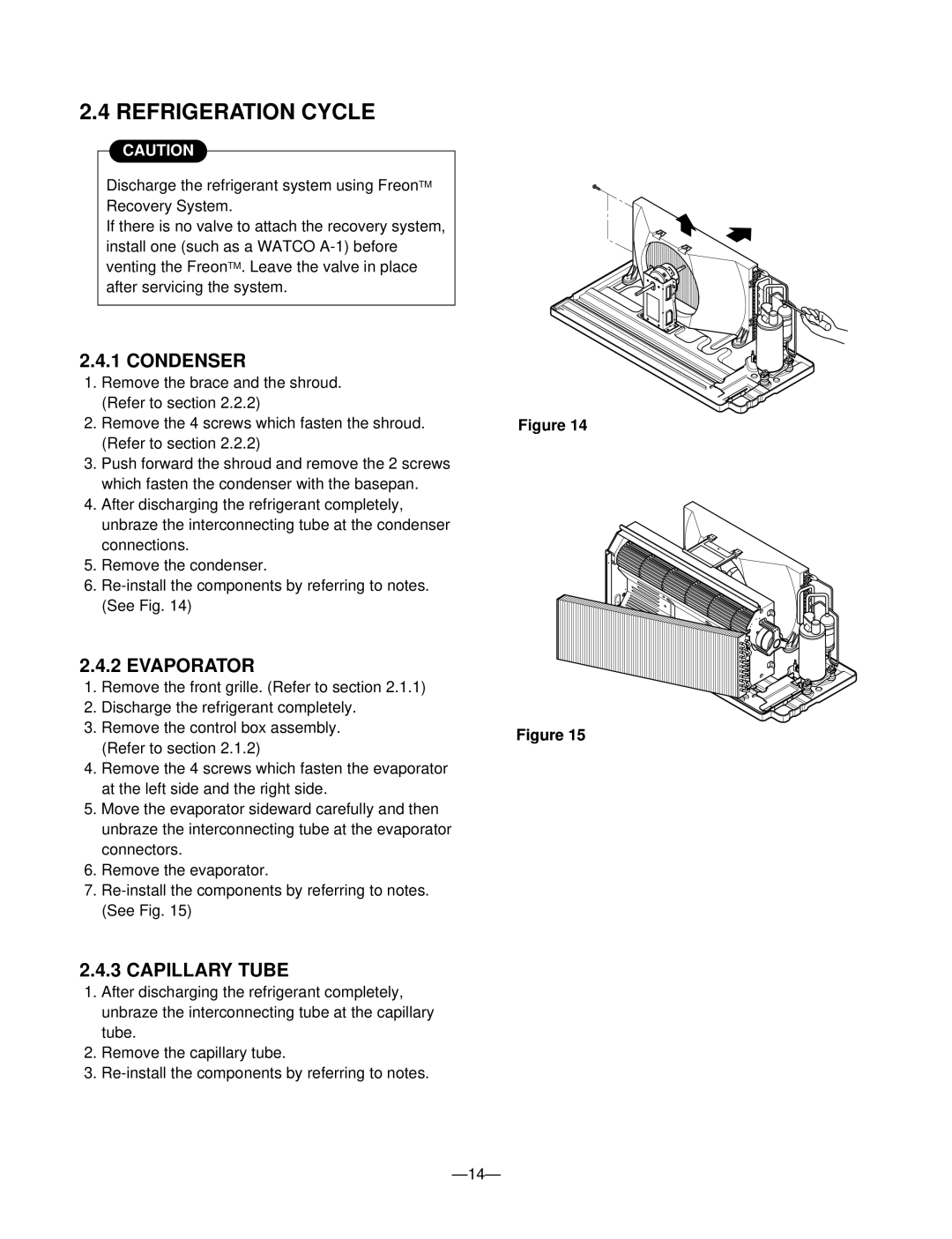
2.4.1 CONDENSER
1.Remove the brace and the shroud. (Refer to section 2.2.2)
2.Remove the 4 screws which fasten the shroud. (Refer to section 2.2.2)
3.Push forward the shroud and remove the 2 screws which fasten the condenser with the basepan.
4.After discharging the refrigerant completely, unbraze the interconnecting tube at the condenser connections.
5.Remove the condenser.
6.
2.4.2 EVAPORATOR
1.Remove the front grille. (Refer to section 2.1.1)
2.Discharge the refrigerant completely.
3.Remove the control box assembly. (Refer to section 2.1.2)
4.Remove the 4 screws which fasten the evaporator at the left side and the right side.
5.Move the evaporator sideward carefully and then unbraze the interconnecting tube at the evaporator connectors.
6.Remove the evaporator.
7.
2.4.3 CAPILLARY TUBE
1.After discharging the refrigerant completely, unbraze the interconnecting tube at the capillary tube.
2.Remove the capillary tube.
3.
Figure 14
Figure 15