3-1-7 Connecting the Gateway to a Remote Router
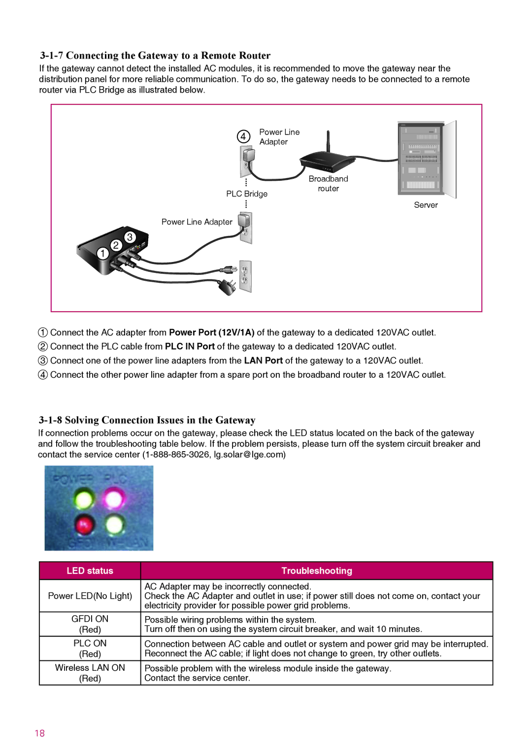
If the gateway cannot detect the installed AC modules, it is recommended to move the gateway near the distribution panel for more reliable communication. To do so, the gateway needs to be connected to a remote router via PLC Bridge as illustrated below.
|
| 4 | Power Line |
|
|
| Adapter |
| |
|
|
|
| |
|
|
|
| Broadband |
|
| PLC Bridge | router | |
|
|
| ||
|
|
|
| Server |
|
| Power Line Adapter |
|
|
1 | 2 | 3 |
|
|
1Connect the AC adapter from Power Port (12V/1A) of the gateway to a dedicated 120VAC outlet.
2Connect the PLC cable from PLC IN Port of the gateway to a dedicated 120VAC outlet.
3Connect one of the power line adapters from the LAN Port of the gateway to a 120VAC outlet.
4Connect the other power line adapter from a spare port on the broadband router to a 120VAC outlet.
3-1-8 Solving Connection Issues in the Gateway
If connection problems occur on the gateway, please check the LED status located on the back of the gateway and follow the troubleshooting table below. If the problem persists, please turn off the system circuit breaker and contact the service center
LED status | Troubleshooting |
|
|
| AC Adapter may be incorrectly connected. |
Power LED(No Light) | Check the AC Adapter and outlet in use; if power still does not come on, contact your |
| electricity provider for possible power grid problems. |
GFDI ON | Possible wiring problems within the system. |
(Red) | Turn off then on using the system circuit breaker, and wait 10 minutes. |
PLC ON | Connection between AC cable and outlet or system and power grid may be interrupted. |
(Red) | Reconnect the AC cable; if light does not change to green, try other outlets. |
Wireless LAN ON | Possible problem with the wireless module inside the gateway. |
(Red) | Contact the service center. |
18
