3.5 SYSTEM WIRING
Battery Back-Up Wiring Installation
The system can be equipped with external batteries for proper operation when local AC power fails. The
The External batteries must provide 24 Volts DC. This is generally accomplished by connecting two 12 volts batteries in a series arrangement. Battery operation is controlled by the MFB. The MFB will provide charging current(maximum 0.5 amp) to the batteries during normal AC power operation. The MFB will automatically stop the battery operation when AC power
The system operating time by external batteries is depend on several elements as follows, battery charge state, condition of the batteries, capacity of the batteries, and the system configuration(number of station ports).
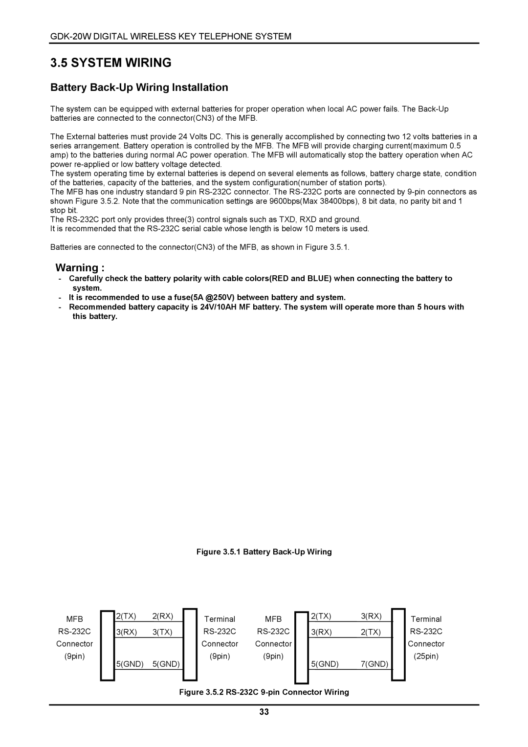
The MFB has one industry standard 9 pin
The
Batteries are connected to the connector(CN3) of the MFB, as shown in Figure 3.5.1.
Warning :
-Carefully check the battery polarity with cable colors(RED and BLUE) when connecting the battery to system.
-It is recommended to use a fuse(5A @250V) between battery and system.
-Recommended battery capacity is 24V/10AH MF battery. The system will operate more than 5 hours with this battery.
Figure 3.5.1 Battery Back-Up Wiring
MFB
Connector
(9pin)
2(TX) 2(RX) 3(RX) 3(TX)
5(GND) 5(GND)
Terminal MFB
Connector Connector
(9pin) (9pin)
2(TX) 3(RX)
3(RX) 2(TX)
5(GND) 7(GND)
Terminal
Connector
(25pin)
Figure 3.5.2 RS-232C 9-pin Connector Wiring
33