3.6.2.2 Examples
A. Example 1 - Centralizing Base Stations
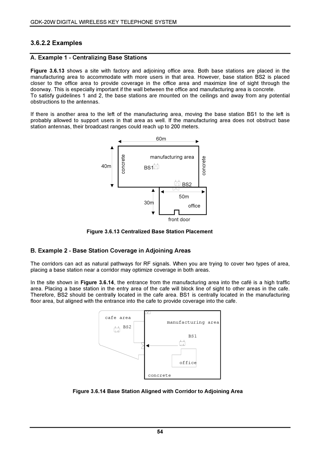
Figure 3.6.13 shows a site with factory and adjoining office area. Both base stations are placed in the manufacturing area to accommodate with more users in that area. However, base station BS2 is placed closer to the office area to provide coverage in the office area and maximize line of sight through the doorway. This is especially important if the wall between the office and manufacturing area is concrete.
To satisfy guidelines 1 and 2, the base stations are mounted on the ceilings and away from any potential obstructions to the antennas.
If there is another area to the left of the manufacturing area, moving the base station BS1 to the left is probably allowed to support users in that area as well. If the manufacturing area does not obstruct base station antennas, their broadcast ranges could reach up to 200 meters.
40m
concrete
60m
manufacturing area
BS1
| BS2 | |
30m | 50m | |
office | ||
| ||
| front door |
concrete
Figure 3.6.13 Centralized Base Station Placement
B. Example 2 - Base Station Coverage in Adjoining Areas
The corridors can act as natural pathways for RF signals. When you are trying to cover two types of area, placing a base station near a corridor may optimize coverage in both areas.
In the site shown in Figure 3.6.14, the entrance from the manufacturing area into the café is a high traffic area. Placing a base station in the entry area of the cafe will block line of sight to other areas in the cafe. Therefore, BS2 should be centrally located in the cafe area. BS1 is centrally located in the manufacturing floor area, but aligned with the entrance into the cafe to provide coverage into the cafe.
cafe area
BS2
manufacturing area
BS1
office
concrete
Figure 3.6.14 Base Station Aligned with Corridor to Adjoining Area
54