INSTALLATION
VIDEO CONNECTIONS
Use coaxial cables when connecting a camera and a monitor to this VCR.
Note: Long cable runs to distant cameras may cause signal deterioration and/or sync discrep- ancies. If these problems occur, use video line amplifiers and/or cameras having
Video Input
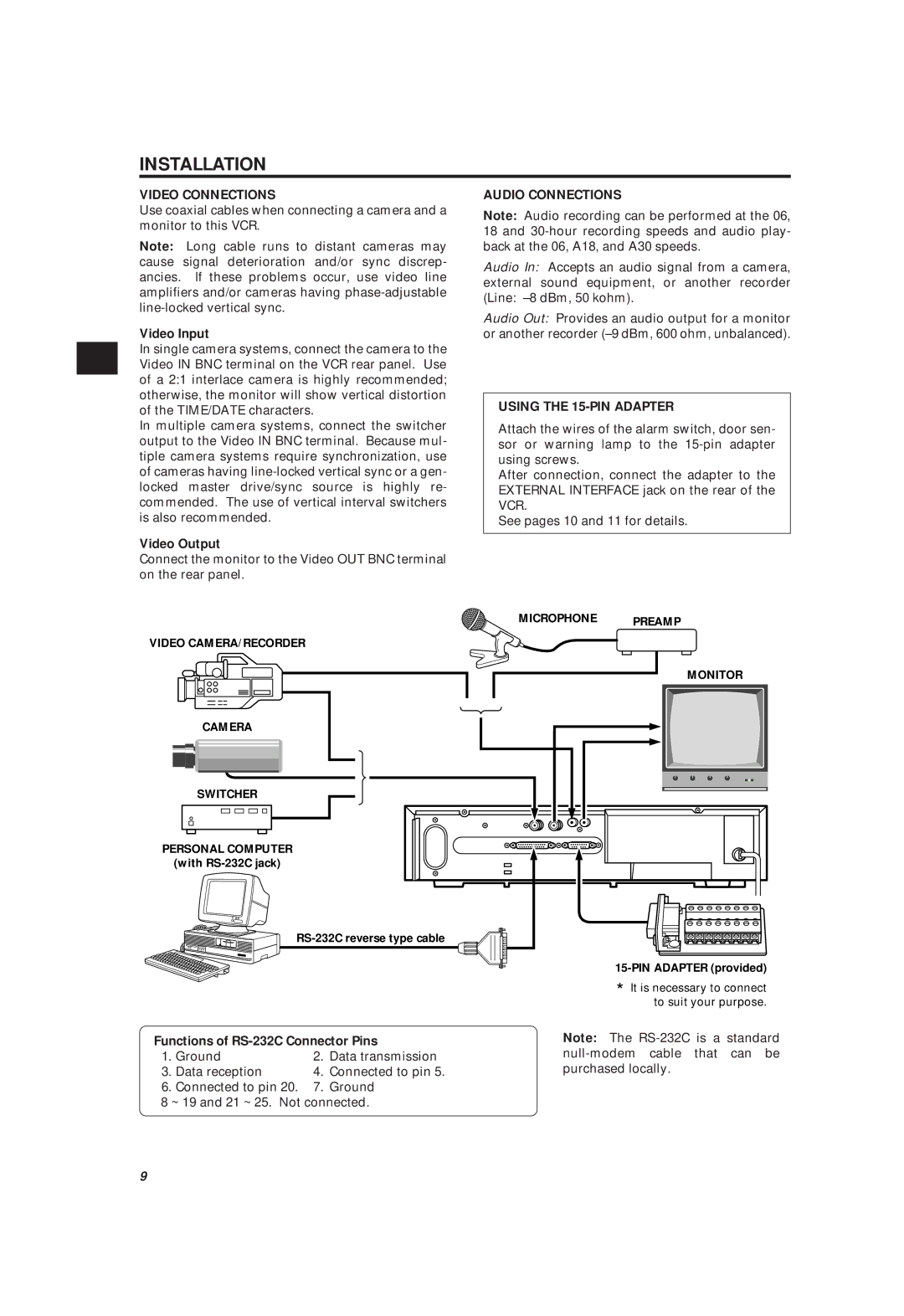
In single camera systems, connect the camera to the Video IN BNC terminal on the VCR rear panel. Use of a 2:1 interlace camera is highly recommended; otherwise, the monitor will show vertical distortion of the TIME/DATE characters.
In multiple camera systems, connect the switcher output to the Video IN BNC terminal. Because mul- tiple camera systems require synchronization, use of cameras having
Video Output
Connect the monitor to the Video OUT BNC terminal on the rear panel.
AUDIO CONNECTIONS
Note: Audio recording can be performed at the 06, 18 and
Audio In: Accepts an audio signal from a camera, external sound equipment, or another recorder (Line:
Audio Out: Provides an audio output for a monitor or another recorder
USING THE 15-PIN ADAPTER
Attach the wires of the alarm switch, door sen- sor or warning lamp to the
After connection, connect the adapter to the EXTERNAL INTERFACE jack on the rear of the VCR.
See pages 10 and 11 for details.
MICROPHONE | PREAMP |
| |
VIDEO CAMERA/RECORDER |
|
| MONITOR |
CAMERA |
|
SWITCHER |
|
PERSONAL COMPUTER |
|
(with |
|
| |
| |
| * It is necessary to connect |
| to suit your purpose. |
Functions of RS-232C Connector Pins
1. | Ground | 2. | Data transmission |
3. | Data reception | 4. | Connected to pin 5. |
6.Connected to pin 20. 7. Ground
8~ 19 and 21 ~ 25. Not connected.
Note: The
9