EXTERNAL CONNECTIONS
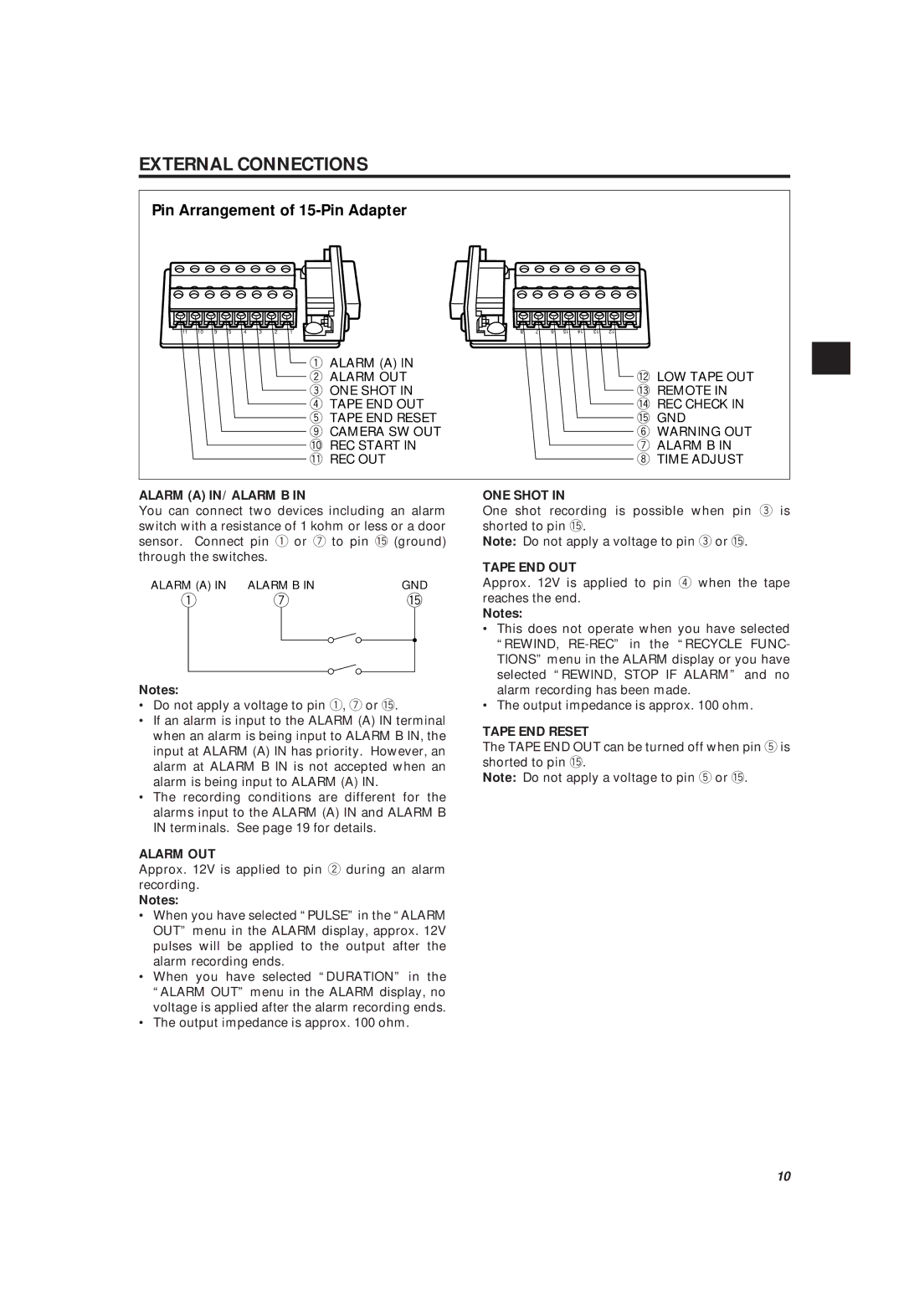
Pin Arrangement of 15-Pin Adapter
11 | 10 | 9 | 5 | 4 | 3 | 2 | 1 |
q ALARM (A) IN w ALARM OUT e ONE SHOT IN r TAPE END OUT t TAPE END RESET o CAMERA SW OUT !0REC START IN !1REC OUT
ALARM (A) IN/ ALARM B IN
You can connect two devices including an alarm switch with a resistance of 1 kohm or less or a door sensor. Connect pin q or u to pin !5(ground) through the switches.
ALARM (A) IN | ALARM B IN | GND | ||
q | u | !5 | ||
|
|
|
|
|
|
|
|
|
|
Notes:
•Do not apply a voltage to pin q, u or !5.
•If an alarm is input to the ALARM (A) IN terminal when an alarm is being input to ALARM B IN, the input at ALARM (A) IN has priority. However, an alarm at ALARM B IN is not accepted when an alarm is being input to ALARM (A) IN.
•The recording conditions are different for the alarms input to the ALARM (A) IN and ALARM B IN terminals. See page 19 for details.
ALARM OUT
Approx. 12V is applied to pin w during an alarm recording.
Notes:
•When you have selected “PULSE” in the “ALARM OUT” menu in the ALARM display, approx. 12V pulses will be applied to the output after the alarm recording ends.
•When you have selected “DURATION” in the “ALARM OUT” menu in the ALARM display, no voltage is applied after the alarm recording ends.
•The output impedance is approx. 100 ohm.
8 | 7 | 6 | 15 | 14 | 13 | 12 |
!2LOW TAPE OUT !3REMOTE IN !4REC CHECK IN !5GND
y WARNING OUT u ALARM B IN i TIME ADJUST
ONE SHOT IN
One shot recording is possible when pin e is shorted to pin !5.
Note: Do not apply a voltage to pin e or !5.
TAPE END OUT
Approx. 12V is applied to pin r when the tape reaches the end.
Notes:
•This does not operate when you have selected “REWIND,
•The output impedance is approx. 100 ohm.
TAPE END RESET
The TAPE END OUT can be turned off when pin t is shorted to pin !5.
Note: Do not apply a voltage to pin t or !5.
10