Installation
External Equipment Connections
NOTE: All cables shown are not included with the Monitor
VCR Setup
-To avoid picture noise (interference), leave an adequate distance between the VCR and Monitor
-Use the ISM Method (on the Option menu) feature to avoid having a fixed image remain on the screen for a long period of time. Typically a frozen still picture from a VCR. If the 4:3 picture format is used; the fixed images on the sides of the screen may remain visible on the screen.
Connection Option 1
Set VCR output switch to 3 or 4 and then tune
Monitor to the same channel number.
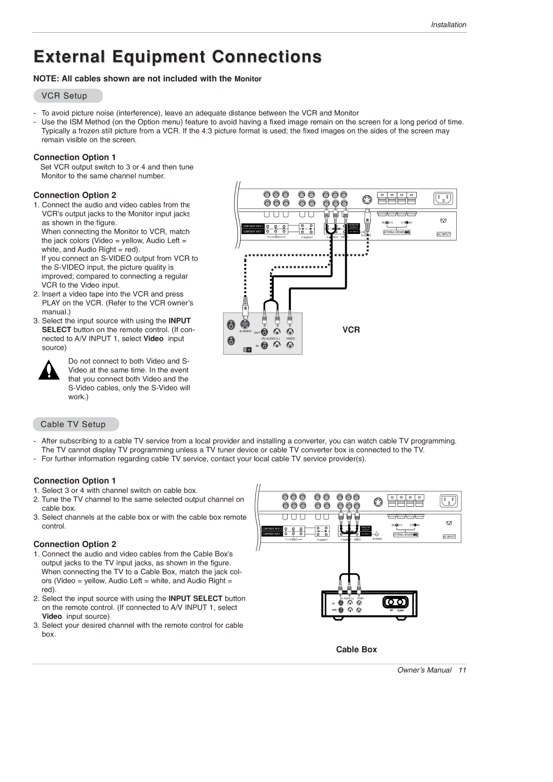
Connection Option 2 |
|
|
|
|
|
|
|
|
|
|
|
1. Connect the audio and video cables from the |
|
|
|
|
|
|
|
|
|
|
|
VCR's output jacks to the Monitor input jacks, |
|
|
|
|
|
|
|
|
|
|
|
as shown in the figure. |
|
|
|
|
|
|
|
| MONITOR | ( ) R ( ) | ( ) L ( ) |
When connecting the Monitor to VCR, match RGB INPUT | COMPONENT INPUT 2 | PB | PR | R | L | R |
| OUTPUT |
|
| |
RGB OUTPUT | Y | L/MONO |
| AC INPUT | |||||||
| COMPONENT INPUT 1 |
|
|
|
|
|
| A/V INPUT | EXTERNAL SPEAKER | ||
the jack colors (Video = yellow, Audio Left = |
|
| VIDEO |
|
| AUDIO |
| AUDIO | VIDEO |
|
|
|
|
|
|
|
|
|
|
|
|
| |
white, and Audio Right = red). |
|
|
|
|
|
|
|
|
|
|
|
If you connect an |
|
|
|
|
|
|
|
|
|
|
|
the |
|
|
|
|
|
|
|
|
|
|
|
improved; compared to connecting a regular |
|
|
|
|
|
|
|
|
|
|
|
VCR to the Video input. |
|
|
|
|
|
|
|
|
|
|
|
2. Insert a video tape into the VCR and press |
|
|
|
|
|
|
|
|
|
|
|
PLAY on the VCR. (Refer to the VCR owner’s |
|
|
|
|
|
|
|
|
|
|
|
manual.) |
|
|
|
|
|
|
|
|
|
|
|
3. Select the input source with using the INPUT |
|
|
|
|
|
|
|
| VCR |
|
|
SELECT button on the remote control. (If con- | OUT |
|
|
|
|
|
|
|
| ||
nected to A/V INPUT 1, select Video input |
| (R) AUDIO (L) |
| VIDEO |
|
|
|
|
|
| |
source) |
| IN |
|
|
|
|
|
|
|
|
|
Do not connect to both Video and S- Video at the same time. In the event that you connect both Video and the
Cable TV Setup
-After subscribing to a cable TV service from a local provider and installing a converter, you can watch cable TV programming. The TV cannot display TV programming unless a TV tuner device or cable TV converter box is connected to the TV.
-For further information regarding cable TV service, contact your local cable TV service provider(s).
Connection Option 1 |
|
|
|
|
|
|
|
|
|
|
|
1. Select 3 or 4 with channel switch on cable box. |
|
|
|
|
|
|
|
|
|
|
|
2. Tune the TV channel to the same selected output channel on |
|
|
|
|
|
|
|
|
|
|
|
cable box. |
|
|
|
|
|
|
|
|
|
|
|
3. Select channels at the cable box or with the cable box remote |
|
|
|
|
|
|
|
|
|
|
|
control. | COMPONENT INPUT 2 |
|
|
|
|
|
|
| OUTPUT | ( ) R ( ) | ( ) L ( ) |
|
|
|
|
|
|
|
|
| MONITOR |
|
|
| Y | PB | PR | R | L | R | L/MONO |
|
| EXTERNAL SPEAKER | |
| COMPONENT INPUT 1 |
|
|
|
|
|
|
| A/V INPUT | ||
| TPUT | VIDEO |
|
|
|
|
| VIDEO |
| AC INPUT | |
Connection Option 2 |
|
|
| AUDIO |
| AUDIO |
|
| |||
|
|
|
|
|
|
|
|
|
|
| |
1.Connect the audio and video cables from the Cable Box's output jacks to the TV input jacks, as shown in the figure.
When connecting the TV to a Cable Box, match the jack col- |
|
|
ors (Video = yellow, Audio Left = white, and Audio Right = |
|
|
red). |
|
|
2. Select the input source with using the INPUT SELECT button |
| (R) AUDIO (L) VIDEO |
on the remote control. (If connected to A/V INPUT 1, select | TV |
|
VCR | RF Cable | |
Video input source) |
|
|
3.Select your desired channel with the remote control for cable box.
Cable Box
Owner’s Manual 11