Introduction
Controls
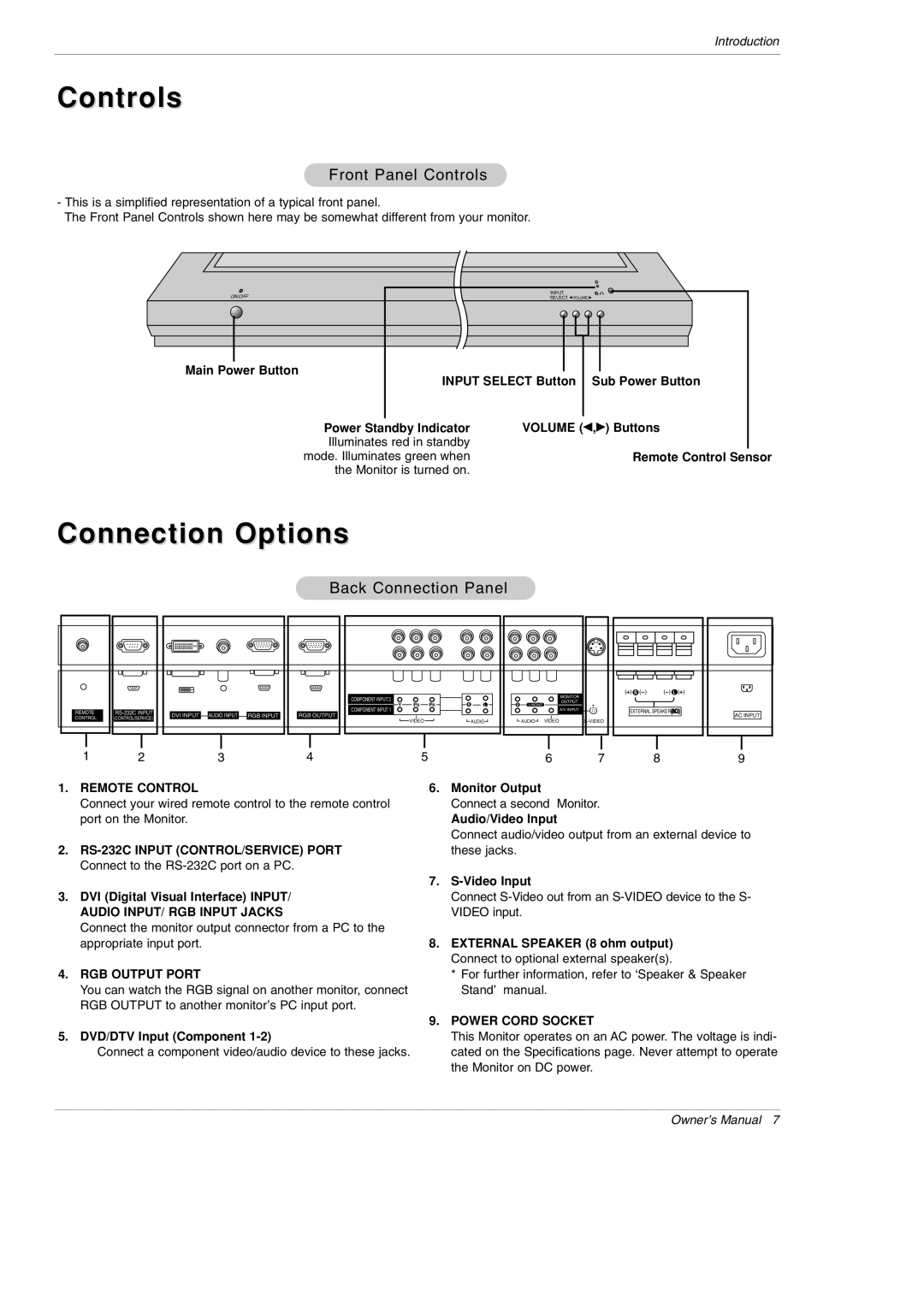
Front Panel Controls
-This is a simplified representation of a typical front panel.
The Front Panel Controls shown here may be somewhat different from your monitor.
ON/OFF | INPUT |
|
SELECT VOLUME |
| |
Main Power Button | INPUT SELECT Button | Sub Power Button |
|
Power Standby Indicator | VOLUME (F,G) Buttons |
Illuminates red in standby |
|
mode. Illuminates green when | Remote Control Sensor |
the Monitor is turned on. |
|
Connection Options
Back Connection Panel
|
|
|
|
|
|
|
|
|
|
|
|
| ( | ) R ( ) | ( | ) L ( | ) |
|
|
|
|
| COMPONENT INPUT 2 |
|
|
|
|
|
|
| MONITOR |
|
|
|
|
|
|
|
|
| PB | PR | R | L | R |
|
| OUTPUT |
|
|
|
| |
|
|
|
|
| Y | L/MONO |
|
|
|
|
|
| |||||
REMOTE | DVI INPUT | AUDIO INPUT | RGB INPUT | COMPONENT INPUT 1 |
|
|
|
|
|
|
| A/V INPUT | EXTERNAL SPEAKER | AC INPUT | |||
CONTROL | (CONTROL/SERVICE) | RGB OUTPUT | VIDEO |
|
| AUDIO |
| AUDIO | VIDEO |
|
|
| |||||
|
|
|
|
|
|
|
|
|
|
|
|
| |||||
1 | 2 |
| 3 |
| 4 | 5 |
|
|
|
|
| 6 | 7 |
| 8 |
| 9 |
1.REMOTE CONTROL
Connect your wired remote control to the remote control port on the Monitor.
2.
3.DVI (Digital Visual Interface) INPUT/ AUDIO INPUT/ RGB INPUT JACKS
Connect the monitor output connector from a PC to the appropriate input port.
4.RGB OUTPUT PORT
You can watch the RGB signal on another monitor, connect RGB OUTPUT to another monitor’s PC input port.
5.DVD/DTV Input (Component
Connect a component video/audio device to these jacks.
6.Monitor Output
Connect a second Monitor.
Audio/Video Input
Connect audio/video output from an external device to these jacks.
7.
Connect
8.EXTERNAL SPEAKER (8 ohm output) Connect to optional external speaker(s).
*For further information, refer to ‘Speaker & Speaker Stand’ manual.
9.POWER CORD SOCKET
This Monitor operates on an AC power. The voltage is indi- cated on the Specifications page. Never attempt to operate the Monitor on DC power.
Owner’s Manual 7
