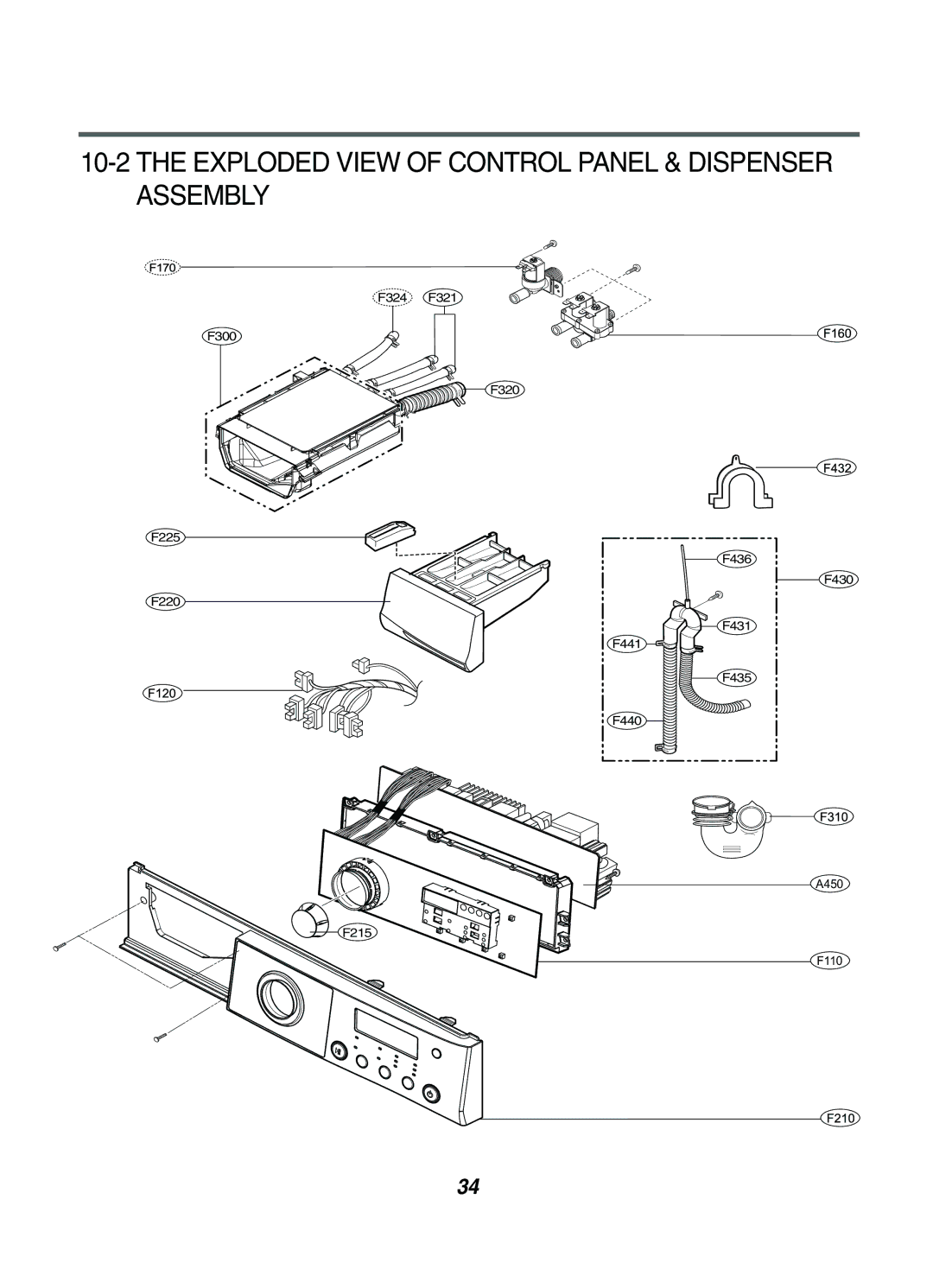
10-2 THE EXPLODED VIEW OF CONTROL PANEL & DISPENSER ASSEMBLY
F324 F321
F300
![]()
![]()
![]()
![]()
![]() F320
F320
F225
F220
F436
F431
F441
F430
F435
F440 ![]()
A450
![]() F215
F215
F110
34
F324 F321
F300
![]()
![]()
![]()
![]()
![]() F320
F320
F225
F220
F436
F431
F441
F430
F435
F440 ![]()
A450
![]() F215
F215
F110
34