Manuals
/
Liebert
/
Computer Equipment
/
Power Supply
Liebert
50 and 60 Hz, S3
user manual
Cabinet Dimensions With Transformer Cabinet
Models:
S3
50 and 60 Hz
1
36
73
73
Download
73 pages
29.45 Kb
33
34
35
36
37
38
39
40
Physical Characteristics
Install
Error codes
User Response to UPS Alarms
Optional DC Ground Fault Alarm
Electrical Wiring
Dimension
Maintenance
Configuration Menu Tree
Battery Times
Page 36
Image 36
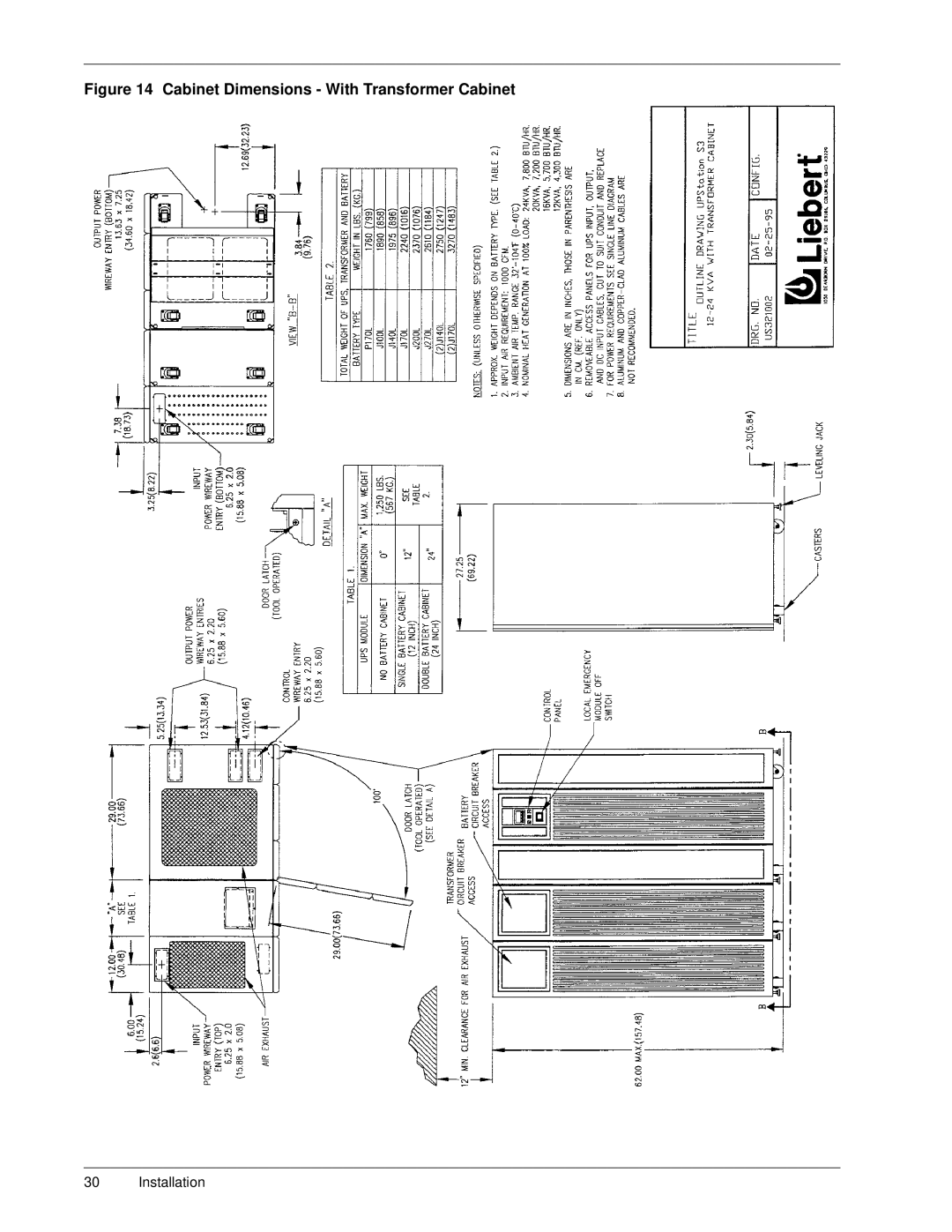
Figure 14 Cabinet Dimensions - With Transformer Cabinet
30 Installation
Page 35
Page 37
Page 36
Image 36
Page 35
Page 37
Contents
UPStation S3
Page
Table of Contents
Êïéïì
Êïéïë
Êïèïì
Êïèïë
LJXUHýì
LJXUHýë
LJXUHýè
LJXUHýç
Page
$ $7717,21ý,167$//56
8VHýDSSURSULDWHýZLUHýVLHVýDQGýDSSURYHGýZLULQJýWHFKQLTXHVâý
Site Planning Data
Additional Notes
Description
Site Planning Data
UPS Cabinet
System Components
Standard UPS Unit
Options
‡ %ROWðRQýEDWWHU\ýFDELQHWñýIDFWRU\ýFRQQHFWHG
Modes of Operation
Safety Precautions
ZRUNLQJýZLWKýWKHý836ï $ $51,1* 7+ý%$775ý,6ý$/$6ý15*,=ïý
HFHVVýPRLVWXUHñýRUýGHEULVï
UPS Installation
Installation Considerations
Unloading and External Inspection
Internal Inspection of the UPS System
Batteries
Equipment Location
167$//$7,21ý7,3
RQýLWVýFDVWHUýZKHHOVï
$ð$&,ý%$775,6ý&$1ý35617ý$ý5,6.ý2ý,5ý
Electrical Wiring
UPS Wire Size Guidelines
Power & Control Wiring
Battery Wiring
Wiring Connections
Wiring Inspection
9HULI\ýWKHýIROORZLQJýFRQQHFWLRQVýKDYHýEHHQýPDGHã
HUHGýIURPýWKHý836ýRXWSXWôñýSOXVýJURXQGï
Copper Aluminum or Copper-Clad Aluminum
Temp F
10.7
28.9
#6 350 MCM
One Line Drawing Single Input Configuration 200/240V In/Out
One Line Drawing Dual Input Configuration 200/240V In/Out
Installation
Installation
Installation
Installation
Installation
Installation
Installation
Installation
Installation
Installation
Cabinet Dimensions
Cabinet Dimensions With Transformer Cabinet
Connecting Terminal Details
Connecting Terminal Details With Transformer Cabinet
Battery Option Details 12 Inch Cabinet
Battery Option Details 24 Inch Cabinet
Field Lug Wiring Terminations
Unloading Instructions
Unloading Instructions 24 Inch Battery Cabinet
Battery Times
Control / Display Panel
LCD Display Description
LCD Display
Initial Start-Up
Êï 836ý0HWHUV Éï $FFHSWý6HWWLQJV
ILJXUDWLRQýLVýRSWLRQDOï
\VWHPï 7RýVWDUWýXQLWñýSXVKýWKHý21ýEXWWRQï
Configuration Screen Default Value
Advanced Configuration Screen Default Value
See 4.0 Features & Options
Æï 3URJUDPPDEOHý,QSXWýFRQWDFWV
1HXWUDOï
System Start-Up
Normal Operation
Battery Operation
UHVXPHýDQGýEDWWHU\ýUHFKDUJLQJýZLOOýEHJLQï
RUýLIýWKHý532ýEXWWRQýLVýSUHVVHGï
UHFKDUJHýUDWHñýLQýRUGHUýWRýRSWLPLHýEDWWHU\ýOLIHï
Static Transfer Switch
Bypass Operation
Configuration Menu Tree
Maintenance Bypass
System Shutdown
Manual Off
Automatic Off
Control Switch Locations
User Response to UPS Alarms
Press ‘ON’ To start system Press -- to check
Check Messages
Time Remaining
Load on
Bypass
Alarm Messages
Alarm Message Meaning Corrective Action
Restart after Low Battery
Shutdown
Procedures in 3.0 Operation
Liebert Global Services
RS-232 Communication Feature
Introduction
Terminal Operation
Factory Installed Options
Field Installable Options
Battery Cabinets
External Battery Cabinets
Output Distribution Panel
Communication Options
SiteNet 1 Shutdown Interface Kits
SiteNet Snmp Simple Network Management Protocol
Internal Modem
Delayed Battery Recharge
Optional DC Ground Fault Alarm
Input Contact Isolator
Optional Remote Status Panel
Optional Power Supply
Floor Anchors
DFFRUGDQFHýZLWKýORFDOýDQGýQDWLRQDOýFRGHýUHTXLUHPHQWVï
RS-232 Connections
Output Distribution Panel Board
Routine Maintenance Requirements
Battery Maintenance
Ëï ,ý/&752/7ý&217$&76ý7+ý6.,1ñý$6+ý,7ý2ý ,00,$7/ý,7+ý$75ï
Physical Characteristics
Battery
System
AC Input
SDFNDJHï
XVWRPHUý5HVSRQVHý&HQWHUï
5HYLVHGãý-XO\ýìääæ
Top
Page
Image
Contents