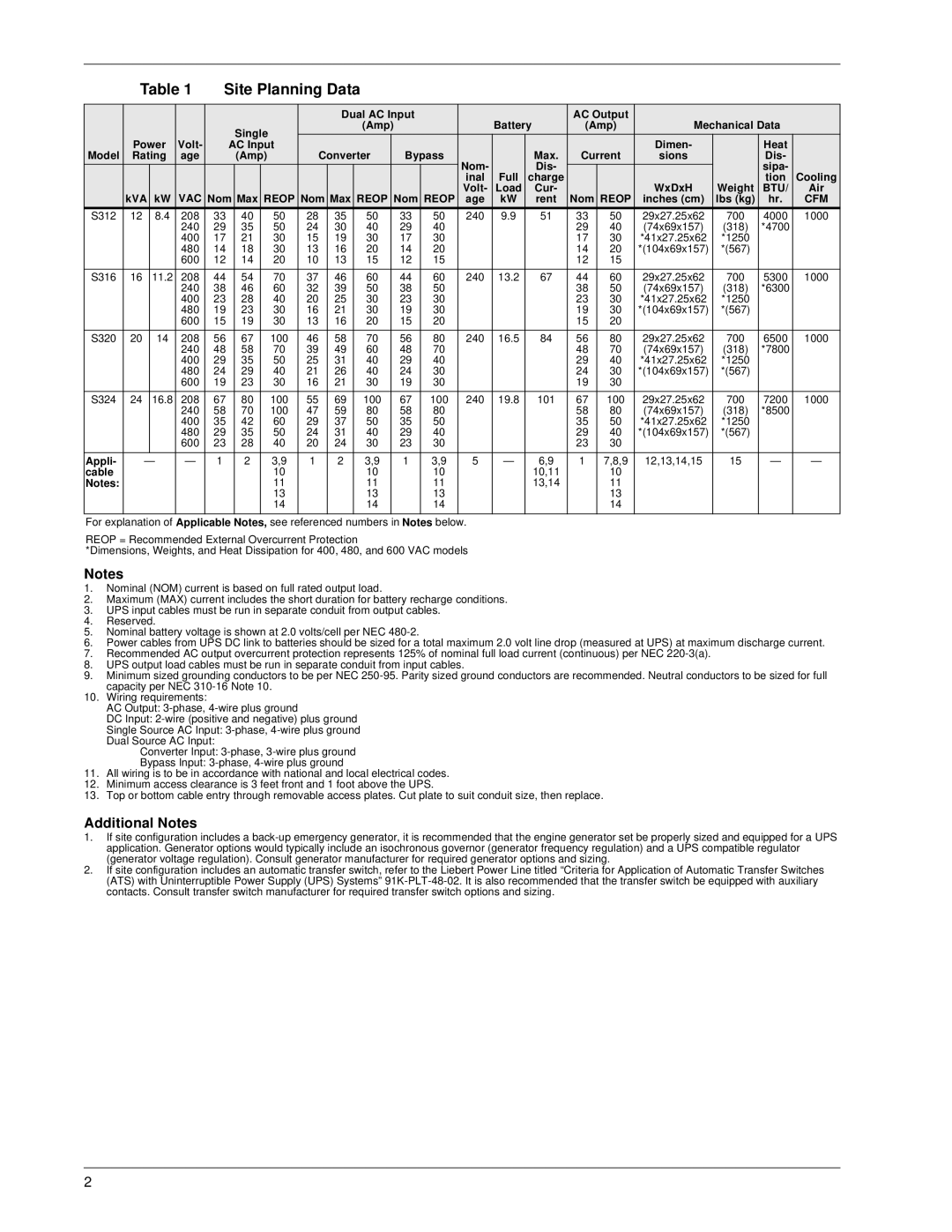
| Table 1 | Site Planning Data |
|
|
|
|
|
|
|
|
|
|
|
|
| |||||||||
|
|
|
|
|
|
|
|
|
|
|
|
|
|
|
|
|
|
|
|
|
|
| ||
|
|
|
|
|
|
|
|
|
| Dual AC Input |
|
| Battery | AC Output | Mechanical Data |
| ||||||||
|
|
|
|
|
|
| Single |
|
|
| (Amp) |
|
|
| (Amp) |
| ||||||||
| Power | Volt- |
| AC Input |
|
|
|
|
|
|
|
|
|
|
|
| Dimen- |
| Heat |
| ||||
Model | Rating | age |
|
| (Amp) | Converter |
| Bypass |
|
| Max. | Current | sions |
| Dis- |
| ||||||||
|
|
|
|
|
|
|
|
|
|
|
|
|
|
|
| Nom- |
| Dis- |
|
|
|
| sipa- |
|
|
|
|
|
|
|
|
|
|
|
|
|
|
|
|
| inal | Full | charge |
|
|
|
| tion | Cooling |
|
|
|
| VAC |
|
|
|
|
|
|
|
|
|
|
| Volt- | Load | Cur- |
|
| WxDxH | Weight | BTU/ | Air |
| kVA | kW | Nom | Max | REOP | Nom | Max | REOP | Nom | REOP | age | kW | rent | Nom | REOP | inches (cm) | lbs (kg) | hr. | CFM | |||||
S312 | 12 |
| 8.4 | 208 | 33 |
| 40 | 50 | 28 | 35 |
| 50 |
| 33 | 50 | 240 | 9.9 | 51 | 33 | 50 | 29x27.25x62 | 700 | 4000 | 1000 |
|
|
|
| 240 | 29 |
| 35 | 50 | 24 | 30 |
| 40 |
| 29 | 40 |
|
|
| 29 | 40 | (74x69x157) | (318) | *4700 |
|
|
|
|
| 400 | 17 |
| 21 | 30 | 15 | 19 |
| 30 |
| 17 | 30 |
|
|
| 17 | 30 | *41x27.25x62 | *1250 |
|
|
|
|
|
| 480 | 14 |
| 18 | 30 | 13 | 16 |
| 20 |
| 14 | 20 |
|
|
| 14 | 20 | *(104x69x157) | *(567) |
|
|
|
|
|
| 600 | 12 |
| 14 | 20 | 10 | 13 |
| 15 |
| 12 | 15 |
|
|
| 12 | 15 |
|
|
|
|
|
|
|
|
|
|
|
|
|
|
|
|
|
|
|
|
|
|
|
|
|
|
|
|
|
S316 | 16 |
| 11.2 | 208 | 44 |
| 54 | 70 | 37 | 46 |
| 60 |
| 44 | 60 | 240 | 13.2 | 67 | 44 | 60 | 29x27.25x62 | 700 | 5300 | 1000 |
|
|
|
| 240 | 38 |
| 46 | 60 | 32 | 39 |
| 50 |
| 38 | 50 |
|
|
| 38 | 50 | (74x69x157) | (318) | *6300 |
|
|
|
|
| 400 | 23 |
| 28 | 40 | 20 | 25 |
| 30 |
| 23 | 30 |
|
|
| 23 | 30 | *41x27.25x62 | *1250 |
|
|
|
|
|
| 480 | 19 |
| 23 | 30 | 16 | 21 |
| 30 |
| 19 | 30 |
|
|
| 19 | 30 | *(104x69x157) | *(567) |
|
|
|
|
|
| 600 | 15 |
| 19 | 30 | 13 | 16 |
| 20 |
| 15 | 20 |
|
|
| 15 | 20 |
|
|
|
|
|
|
|
|
|
|
|
|
|
|
|
|
|
|
|
|
|
|
|
|
|
|
|
|
|
S320 | 20 |
| 14 | 208 | 56 |
| 67 | 100 | 46 | 58 |
| 70 |
| 56 | 80 | 240 | 16.5 | 84 | 56 | 80 | 29x27.25x62 | 700 | 6500 | 1000 |
|
|
|
| 240 | 48 |
| 58 | 70 | 39 | 49 |
| 60 |
| 48 | 70 |
|
|
| 48 | 70 | (74x69x157) | (318) | *7800 |
|
|
|
|
| 400 | 29 |
| 35 | 50 | 25 | 31 |
| 40 |
| 29 | 40 |
|
|
| 29 | 40 | *41x27.25x62 | *1250 |
|
|
|
|
|
| 480 | 24 |
| 29 | 40 | 21 | 26 |
| 40 |
| 24 | 30 |
|
|
| 24 | 30 | *(104x69x157) | *(567) |
|
|
|
|
|
| 600 | 19 |
| 23 | 30 | 16 | 21 |
| 30 |
| 19 | 30 |
|
|
| 19 | 30 |
|
|
|
|
|
|
|
|
|
|
|
|
|
|
|
|
|
|
|
|
|
|
|
|
|
|
|
|
|
S324 | 24 |
| 16.8 | 208 | 67 |
| 80 | 100 | 55 | 69 |
| 100 |
| 67 | 100 | 240 | 19.8 | 101 | 67 | 100 | 29x27.25x62 | 700 | 7200 | 1000 |
|
|
|
| 240 | 58 |
| 70 | 100 | 47 | 59 |
| 80 |
| 58 | 80 |
|
|
| 58 | 80 | (74x69x157) | (318) | *8500 |
|
|
|
|
| 400 | 35 |
| 42 | 60 | 29 | 37 |
| 50 |
| 35 | 50 |
|
|
| 35 | 50 | *41x27.25x62 | *1250 |
|
|
|
|
|
| 480 | 29 |
| 35 | 50 | 24 | 31 |
| 40 |
| 29 | 40 |
|
|
| 29 | 40 | *(104x69x157) | *(567) |
|
|
|
|
|
| 600 | 23 |
| 28 | 40 | 20 | 24 |
| 30 |
| 23 | 30 |
|
|
| 23 | 30 |
|
|
|
|
|
|
|
|
|
|
|
|
|
|
|
|
|
|
|
|
|
|
|
|
|
|
|
|
|
Appli- |
| — | — | 1 |
| 2 | 3,9 | 1 | 2 |
| 3,9 |
| 1 | 3,9 | 5 | — | 6,9 | 1 | 7,8,9 | 12,13,14,15 | 15 | — | — | |
cable |
|
|
|
|
|
|
| 10 |
|
|
| 10 |
|
| 10 |
|
| 10,11 |
| 10 |
|
|
|
|
Notes: |
|
|
|
|
|
|
| 11 |
|
|
| 11 |
|
| 11 |
|
| 13,14 |
| 11 |
|
|
|
|
|
|
|
|
|
|
|
| 13 |
|
|
| 13 |
|
| 13 |
|
|
|
| 13 |
|
|
|
|
|
|
|
|
|
|
|
| 14 |
|
|
| 14 |
|
| 14 |
|
|
|
| 14 |
|
|
|
|
|
|
|
|
|
|
|
|
|
|
|
|
|
|
|
|
|
|
|
|
|
|
|
|
|
For explanation of Applicable Notes, see referenced numbers in Notes below.
REOP = Recommended External Overcurrent Protection
*Dimensions, Weights, and Heat Dissipation for 400, 480, and 600 VAC models
Notes
1.Nominal (NOM) current is based on full rated output load.
2.Maximum (MAX) current includes the short duration for battery recharge conditions.
3.UPS input cables must be run in separate conduit from output cables.
4.Reserved.
5.Nominal battery voltage is shown at 2.0 volts/cell per NEC
6.Power cables from UPS DC link to batteries should be sized for a total maximum 2.0 volt line drop (measured at UPS) at maximum discharge current.
7.Recommended AC output overcurrent protection represents 125% of nominal full load current (continuous) per NEC
8.UPS output load cables must be run in separate conduit from input cables.
9.Minimum sized grounding conductors to be per NEC
10.Wiring requirements:
AC Output:
DC Input:
Single Source AC Input:
Converter Input:
Bypass Input:
11.All wiring is to be in accordance with national and local electrical codes.
12.Minimum access clearance is 3 feet front and 1 foot above the UPS.
13.Top or bottom cable entry through removable access plates. Cut plate to suit conduit size, then replace.
Additional Notes
1.If site configuration includes a
2.If site configuration includes an automatic transfer switch, refer to the Liebert Power Line titled “Criteria for Application of Automatic Transfer Switches (ATS) with Uninterruptible Power Supply (UPS) Systems”
2